
Alteas ONE Net Installation Manual

26 /
INSTALLATION
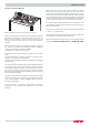
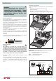
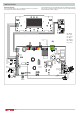
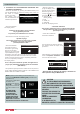
Electrical diagram
For increased safety, ask a qualifi ed technician to perform a
thorough check of the electrical system.
The manufacturer is not responsible for any damage caused by
the lack of a suitable earthing system or by the malfunctioning
of the electricity mains supply.
BUS
TB
FLOOR
TA2
230 V
SETNK SOL TA1
230 V
230 V 230 V 230 V 230 V
N L
N
L
GAS VALVE
Modulating
fan
Bk
Bk
Modulating circulation
pump
Br
Bk
Gry
Bk
Bl
Br
Bk
D.H.W.
flow switch
Water
pressure sensor
Diverter valve
Bl
Rd
Wh
Br
Rd
Bl
Bl
C.H. return
temperature
probe
C.H. flow
temperature
probe
Rd
Detection/Ignition
electrode
GATEWAY WIFI
Bk= Black
Rd = Red
Gr = Green
Bl = Blue
Br = Brown
Wh = White
Gry = Grey