
Technical information


22
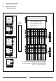
7. MISCELLANEOUS
7.1 WIRING DIAGRAM FOR
TWO HEATING ZONES
V4043H
VALVE
BROWN
8
BLUE
2
GREY
9
ORANGE
10
GREEN/YELLOW
3
Honeywell ST 699B 1002
63 N L
Link L-5-8
ST 6400/ST 6300 ST 6200 3 4 N L
Drayton Tempus 7 3 4 N L
Horstmann 425, 525, 527
14 EN L
Link L-2-5
Landis & Gyr RWB2
34 N L
Glowworm Mastermind
Landis & Gyr RWB20
34 N L
Microgyr
Potterton Miniminder 3 4 N L
Potterton EP2000/3000 - 3 4 N L
Link L-5 EP2001/3001
Randall 102/102 E 1 2 E 5 6
Link 3-6
Randall 4033
42 E7 6
Link 1-6
Randall 701, 702
31 EN L
Link L-6-5
Sangamo M5 1 8 E 4 3
Link 1-6
Sangamo 410 Form 1
18 E4 3
Link 3-6
PROGRAMMER
64321
Pegler Sunvic
25 EN L
SP 50/100 (Link L-3)
Switchmaster
14 N L
Symphony, Sonata
Switchmaster 400, 600 3 1 N L
SWITCHMASTER 805, 900
31 N L
Sunvic ET 1451
74 E1 2
Link 2-3-6
Sunvic DHP 2201 6 3 E 1 2
Towerchron FP
610 2 1
Link 1-5/4-7-9
Towerchron MP
610 2 1
Link 1-4/6-11
Towerchron 2000 HW HTG
NL
ON ON
ACL LS522, LS722 3 4 N L
Randall 922, 972
36 EN L
Link L-2-5
Randall 3020 P
42 EN L
and 3060
PROGRAMMER
64321
ENLmicroGENUS 23-27 MFFI
BOILER
9 10 3 2
240V
MAINS INPUT (3 AMP)
L1
N2
E3
• 1
• 2
• 3
• 4
• 5
• 6
• 7
• 8
• 9
• 10
TYPICAL
JUNCTION BOX
T6360B
ROOM
THERMOSTAT
16
38
22
ZONE 2
V4043H
VALVE
BROWN
5
BLUE
2
GREY
9
ORANGE
10
GREEN/YELLOW
3
T6360B
ROOM
THERMOSTAT
14
35
22
ZONE1
ZONE 1
ZONE 1
ZONE 2 ZONE 2
1
BOILER ELECTRICAL SUPPLY CABLE
Remove internal time clock plug
from the the P.C.B. then connect
room stat terminal block on the
reverse of the boiler control panel
(see section 2.10)
to 9 + 10 on
the junction box.
If a room thermostat is not requied on Zone 1, insert a link
between 4 + 5 on the junction box.
If a room thermostat is not requied on Zone 2, insert a link
between 6 + 8 on the junction box.
Based on Honeywell controls
SH010A