Installation Instructions Type C Boilers G.C.
TABLE OF CONTENTS 1. GENERAL INFORMATION 1.1 GENERAL INSTRUCTIONS 1.2 OVERALL VIEW 2. INSTALLATION 2.1 2.2 2.3 2.4 2.5 2.6 2.7 2.8 2.9 2.10 2.11 2.12 REFERENCE STANDARDS SITING THE APPLIANCE OVERALL DIMENSIONS CLEARANCES MOUNTING THE APPLIANCE ELECTRICAL CONNECTION GAS CONNECTION WATER CONNECTIONS FLUE CONNECTION ROOM THERMOSTAT CONNECTION ELECTRICAL/SYSTEM DIAGRAMS WATER CIRCUIT DIAGRAMS 3. COMMISSIONING 3.1 3.2 3.3 3.4 3.5 3.6 3.7 3.8 3.
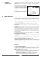
1. GENERAL INFORMATION This manual is an integral and essential part of the product. It should be kept with the appliance so that it can be consulted by the user and our authorised personnel. Please carefully read the instructions and notices about the unit contained in this manual, as they provide important infor mation regarding the safe installation, use and maintenance of the product. For operating instructions please consult the separate User’s Manual. CO034A 1.
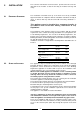
5 - If called for by point. 3, dismantling and cleaning of the combustion chamber. 6 - If called for by point. 4, dismantling and cleaning of the burner jets. 7 - Visual check of the primary heat exchanger: - check for overheating in the blade assembly; - clean the exhaust fan if needed. 8 - Adjustment of the flow rate of the gas: flow rate for lighting, partial load and full load. 9 - Check of the heating safety systems: - safety device for maximum temperature; - safety device for maximum pressure.
2. INSTALLATION The technical information and instructions provided herein below are intended for the installer so that the unit may be installed correctly and safely. 2.1 REFERENCE STANDARDS The installation and initial start up of the boiler must be by a CORGI Approved Installer in compliance with the installation standards currently in effect, as well as with any and all local health and safety standards i.e.. CORGI .
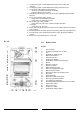
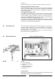
2.3 OVERALL DIMENSIONS LEGEND: A = Central Heating Flow (3/4”) B = Domestic Hot Water Outlet (1/2”) C = Gas Inlet (3/4”) D = Domestic Cold Water Inlet (1/2”) E = Central Heating Return (3/4”) 2.4 CLEARANCES In order to allow for access to the interior of the boiler for maintenance pur poses, the boiler must be installed in compliance with the minimum clearances indicated in FIG. 2.2 FIG. 2.1 QT002A 2.
marked “L”. Note: The diagrams for the electrical system are indicated in section 2.11. Warning, this appliance must be earthed. External wiring to the appliance must be carried out by a qualified technician and be in accordance with the current I.E.E. Regulations and applicable local regulations. The Genus range of boilers are supplied for connection to a 230 V~ 50 Hz supply. The supply must be fused at 3 A.
PIPE WORK: Copper tubing to BS EN 1057:1996 is recommended for water pipes. Jointing should be either with capillary soldered or compression fittings. Where possible pipes should have a gradient to ensure air is carried naturally to air release points and water flows naturally to drain taps. The appliance has a built-in automatic air release valve, however it should be ensured as far as possible that the appliance heat exchanger is not a natural collecting point for air.
2.9 FLUE SYSTEM The provision for satisfactory flue termination must be made as described in BS 5440-1. The appliance must be installed so that the flue terminal is exposed to outdoor air. The terminal must not discharge into another room or space such as an outhouse or lean-to. It is important that the position of the terminal allows a free passage of air across it at all times. The terminal should be located with due regard for the damage or discolouration that might occur on buildings in the vicinity.
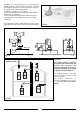
In addition, it is also possible to use a split (twin pipe) system by fitting a special adaptor to the flue connector and using the aperture for the air vent intake located on the top part of the combustion chamber. To utilise the air intake it is necessary to: 1. Remove the bottom of the air intake by cutting it with a suitable knife (see FIG. 2.8); 2. Insert the elbow into the air intake until it reaches the lower end. (There is no need to use gaskets or sealing componds).
TABLE 2.1 23 MFFI Exhaust Type Coaxial Systems ø 60/100 Restrictor ø 43 mm NO Restrictor Maximum Extension Exhaust/Air L min = 0.5 m L max = 2 m L min = 2 m L max = 4 m L=4m Restrictor ø 43 mm NO Restrictor Maximum Extension Exhaust/Air Risk of Condensation Forming Piping insulated Piping not insulated ø 43 restrictor NO ø 43 restrictor NO C12 (xx) C32 (xx) NONE NONE NONE NONE C42 (xx) Exhaust Type 43 m C12 (xy) C32 (xy) Twin Pipe Systems ø 80/80 L max = 11.
In calculating the lengths of the pipes, the maximum length “L” must also take into consideration the values for the exhaust/air intake end terminals, as well as 90° elbows for coaxial systems. The C52 types must comply with the following requirements: 1 - The exhaust/ air intake pipes must have the same diameter of ø 80 mm.
ELECTRICAL DIAGRAM A01 A02 A03 A04 A05 A06 A07 A08 A09 A10 A11 A12 A13 A14 LEGEND: Colours: Gry = Wh = Pnk = Brn = Bl = Blk = Rd/Blk = Grey White Pink Brown Blue Black Red/Black K FIG. 2.
FIG. 2.13 N O R T Q S K J U L M SF014A 2.13 WATER CIRCUIT DIAGRAM LEGEND: FIG. 2.14 1. 2. 3. 4. 5. 6. 7. 8. 9. 10. 11. 12. 13. 14. 15. 16. 17. 18.
3. COMMISSIONING 3.1 INITIAL PREPARATION MTS (GB) Limited support the initiative. Within the information pack you will find a copy of the logbook. It is important that this is completed in the presence of your customer, they are shown how to us it, and it is signed by them. Please instruct your customer that they must have their logbook with them whenever they contact a service engineer or us. Preliminary electrical system checks to ensure electrical safety must be carried out by a competent person i.e.
3.2 CONTROL PANEL LEGEND: 3.3 FR025A A - On/Off knob B - Domestic hot water temperature adjustment knob C - Central heating selection (winter) and temperature adjustment knob D - On/Off L.E.D. (green) E - Fume sensor L.E.D. (yellow) F - Ignition failure (lockout) L.E.D. (red) G - “Economy/Comfort” mode selection knob H - Ignition failure (lockout) and/or overheat reset button I - Overheat L.E.D. (red) J - Low system water level L.E.D. (red) K - Central heating temperature L.E.
3.4. INITIAL START-UP THE CHECKS TO BE RUN BEFORE INITIAL START-UP ARE AS FOLLOWS: 1.
3.6 The flue connector has two apertures, readings can be COMBUSTION ANALYSIS taken for the temperature of the combustion by-products and of the combustion air, as well as of the concentrations of O2 and CO2, etc. . To access these intakes it is necessary to unscrew the front screw and remove the metal plate with sealing gasket.
5. ANTI-FROST DEVICE: The boiler is equipped with a device that, in the event of the water temperature going below 5°C, the 3-way diverter valve switches to domestic hot water and the burner ignites at the minimum power until the boiler water reaches a temperature of about 50°C. This device operates only if the boiler is functioning perfectly and: - the system pressure is sufficient; - the boiler is powered electrically; - the gas is distributed.
4. GAS ADJUSTMENTS Methane Gas G20 Liquid Butane Gas G30 Liquid Propane Gas G31 MJ/m3h mbar mbar 45.67 20 17 80.58 29 20 80.58 37 25 mm mc/h Kg/h 1.30 2.72 ---- 0.77 ---2.02 0.77 ---2.02 mbar 11.0 - 2.0 (*) - 6.0 (*) - 6.0 mc/h Kg/h 1.30 3.15 ---- 0.77 ---2.34 0.77 ---2.31 mbar 11.0 - 1.6 (*) - 4.6 (*) - 6.0 CATEGORY II2H3+ Lower Wobbe Index (15°C;1013mbar) Nominal Delivery Pressure Minimum Delivery Pressure 23 MFFI Main Burner: n.
5. MAINTENANCE It is recommended that the following inspections be carried out on the boiler at least once a year: 1 - Check the seals for the water connections; replacement of any faulty seals. 2 - Check the gas seals; replacement of any faulty gas seals. 3 - Visual check of the entire unit. 4 - Visual check of the combustion process or analysis of combustion byproducts (see section 3.6) and cleaning of the burner if needed. 5 - If called for by point.
240V MAINS INPUT (3 AMP) 8 2 2 T6360B ROOM THERMOSTAT ZONE 2 L 1 N 2 E 3 22 8 E E E E E 4 4 N 7 5 N N N N 3 3 L 6 6 L L L L L ZONE 2 4 Randall 3020 P and 3060 E E HTG ON 1 N N N N 2 2 1 L L L L 1 1 2 2 L L L ZONE 1 PROGRAMMER 2 E E N N N • 3 ZONE 1 3 Randall 922, 972 Link L-2-5 6 4 10 10 3 Towerchron MP Link 1-4/6-11 ACL LS522, LS722 6 Towerchron FP Link 1-5/4-7-9 4 3 HW ON 6 Sunvic DHP 2201 1 1 Towerchron 2000 7 6 Sunv
1 2 C/P Cylinder thermostat Thermal cut-out 1 C/P 2 Not used 23 Sangamo 410 Form 1 Link 3-6 8 8 1 2 2 4 4 4 E E E E E 4 4 N 7 5 N N N N N 3 3 L 6 6 L L L L L 4 Randall 3020 P and 3060 E E HTG ON E E N N N N 2 2 1 1 N N N • 3 L L L L 1 1 2 2 L L L L PROGRAMMER 2 6 4 3 10 10 3 6 Towerchron MP Link 1-4/6-11 Randall 922, 972 Link L-2-5 6 Towerchron FP Link 1-5/4-7-9 3 ACL LS522, LS722 6 Sunvic DHP 2201 4 HW ON 7 Sunvic ET
TECHNICAL INFORMATION Consumption at Nominal Capacity(G20) max/min kW max/min kW % % % % % Kg/h mbar m3/h Gas Consumption after 10 Minutes* (15°C, 1013 mbar) (G30-G31) Temp. of exhaust fumes at nominal capacity CO2 Content m3 Kg/h °C % O2 Content % CO Content Minimum Ambient Temperature Head Loss on Water Side (max) (∆T=20°C) Residual Head of System Heating Temperature Domestic Hot Water Temperature D.H.W. Flow Rate ∆T=35°C D.H.W. Flow Rate ∆T=35°C D.H.W.
Servicing Instructions Type C Boilers G.C.
TABLE OF CONTENTS 2 1. SERVICING INSTRUCTIONS 1.1 REPLACEMENT 1.2 TO GAIN GENERAL ACCESS - Removing the front panel - Removing the sealed chamber frontal cover - Removing the side panels 1.3 ACCESS TO THE COMBUSTION CHAMBER - Removing the combustion cover - Removing the burner and jets - Removing the electrodes - Removing the main heat exchanger - Removing the air pressure switch - Removing the fan - Removing the venturi device 1.
1. SERVICING INSTRUCTIONS To ensure efficient safe operation, it is recommended that the boiler is serviced annually by a competent person. Before starting any servicing work, ensure both the gas and electrical supplies to the boiler are isolated and the boiler is cool. Before and after servicing, a combustion analysis should be made via the flue sampling point (please refer to the Installation Manual for further details).
Removing the sealed chamber frontal cover Removing the side panels 1. Remove the screws “C” (FIG. 1.6); 2. Lift the sealed chamber frontal cover from the locating pins (FIG. 1.7). 1. Remove the four screws “D” for each side panel (FIG.1.8); 2. Pull the panel away from the boiler, then lift the panel up and remove from the boiler (FIG.1.9). FIG. 1.8 D C D C D 18.eps FIG. 1.6 98.tif FIG. 1.9 17 eps 4 FIG. 1.7 97.
1.3 ACCESS TO THE COMBUSTION CHAMBER Removing the combustion cover 1. Remove the screws “E” (FIG. 1.10); 2. Lift off the combustion cover. Fig. 1.12 78 eps Removing the electrodes E E E Before carrying out this procedure, unscrew and slide the burner forward (see previous section). 1. Remove rubber gasket “G” (Fig. 1.13); 2. To remove the detection electrode disconnect the cable at its connection point close to the P.C.B. (Fig. 1.14); FIG. 1.13 FIG. 1.10 99.tif G Removing the burner and jets 1.
3. Remove screw “H” (FIG. 1.15); 4. Gently slide the electrode downward (FIG. 1.16). Removing the main heat exchanger 1. Drain the boiler of water; 2. Release the overheat thermostat sensor “I” (FIG. 1.17); 3. Release the two connection nuts “J” connecting the exchanger to the flow and return pipes (FIG. 1.18); 4. Pull it straight out (FIG. 1.19). FIG. 1.15 H I 51 eps Fig. 1.17 75 eps 11 eps J 76 eps 52 eps FIG. 1.
Removing the air pressure switch Removing the fan 1. Disconnect the electrical connections “K” and silicon pipes “L” from their connection points (FIG. 1.20); 2. Remove screws “M” on the top of the sealed chamber (FIG. 1.21); 3. Unscrew to remove switch from the plate (FIG. 1.22). 1. Disconnect electrical connections “N” and silicon pipes “O” (FIG.1.23); 2. Remove screw “P” and remove the fan collar clamp “Q” (FIG.1.24); 3. Remove screws “R” (FIG.1.25); 4. Remove fan and mounting plate (FIG.1.26). FIG.
1.4 SERVICING AND REMOVAL OF THE GAS VALVE Setting the gas pressures 1 B A VG001Aa 2 D C VG001Ac Setting the minimum and the maximum power of the boiler 1. Check that the supply pressure to the gas valve is a minimum of 20 mbar for natural gas. 2. To do this, remove the screw “A”. Fit the pipe of the pressure gauge to the pressure connection of the gas valve “B”. When you have completed this operation, replace the screw “A” securely into its housing to seal off the gas. 3.
Regulating the heating power for natural gas (G20) model 23 model 27 CG007A Regulating the heating power for butane gas (G30) model 23 model 27 CG008A Regulating the heating power for propane gas (G31) 40 38 36 34 model 23 model 27 CG009A 27 MFFI 23 MFFI TABLE “A” 2.70 2.01 Kg/h 2.00 Kg/h 1.16 0.87 Kg/h 0.85 Kg/h 20 28 mbar 37 mbar 11.0 27.7 mbar 35.5 mbar 2.0 6.0 mbar 7.3 mbar 12 x 0.77 12 x 0.77 3.15 2.34 Kg/h 2.31 Kg/h 1.26 0.94 Kg/h 0.93 Kg/h 20 28 mbar 37 mbar 11.
Removing the spark generator 1. Disconnect ignition leads “T” by pulling upward (FIG. 1.27); 2. Remove the screw “V” (FIG. 1.28); 3. Remove the spark generator (FIG. 1.29). 61.eps T Soft-light Adjustment Max Heating Adjustment VR015A.eps FIG. 1.27 45.eps 10. Remove the pipe from the pressure gauge and connect screw “C” to the pressure outlet in order to seal off the gas. 11. Carefully check the pressure outlets for gas leaks (valve inlet and outlet).
Removing the gas valve 1.6 ACCESS TO THE WATER CIRCUIT 1. Disconnect all the cables from the solenoid and modureg; 2. Remove the spark generator (see previous section); 3. Release the top nut “W” (FIG. 1.30); 4. Remove the screws “X” from the bottom of the gas valve pipe (FIG. 1.31); 5. Remove the gas valve (FIG. 1.32). Important! Before any component is removed, the boiler must be drained of all water. Removing the D.H.W. (secondary) exchanger 1.Remove the screws “Y” (FIG 1.33 + FIG 1.34); 2.
Removing the safety valve 1. Loosen nut “Z” (FIG. 1.36); 2. Unscrew and remove the valve (FIG. 1.37). Removing the main circuit flow switch 1. Remove the cable of the main circuit flow switch “B1” (FIG. 1.40); 2. Remove the screws “C1” (FIG. 1.41); 3. Remove the main circuit flow switch. Z B1 FIG. 1.36 40.eps FIG. 1.40 53.eps C1 FIG. 1.37 37.eps Removing the automatic air vent 1. Unscrew valve top “A1” (FIG. 1.38); 2. Remove valve (Fig 1.39). C1 FIG. 1.41 54.eps A1 12 39.eps Fig. 1.38 41.
Removing the pump 1. 2. 3. 4. 5. 6. 7. Remove the U-clip “ D1” (FIG. 1.41); Remove the retaining clip “E1” (FIG. 1.42); Remove the U-clip “ F1” (FIG. 1.43); Release the nut “G1” (FIG. 1.44); Remove the pipe “H1” (FIG. 1.45); Remove the screws “I1” (FIG. 1.46); Remove the pump (FIG. 1.47). G1 FIG. 1.44 42.eps D1 H1 FIG. 1.41 31.eps FIG. 1.45 32.eps E1 I1 I1 FIG. 1.42 33.eps 35.eps FIG. 1.46 25.eps FIG. 1.47 F1 34.eps B063 FIG. 1.
Removing the pressure gauge Removing the expansion vessel 1. Remove the U-clip “J1” and remove the pressure gauge coupling (FIG. 1.48); 2. Push the pressure gauge through the control panel from the rear (FIG. 1.49). 1. 2. 3. 4. Loosen nuts “K1” and remove the gas pipe (FIG. 1.50); Loosen nut “L1” (FIG. 1.51); Remove back nut “M1” (FIG. 1.52); Remove the expansion vessel (FIG. 1.53). K1 J1 K1 FIG. 1.50 77.eps 34.eps FIG. 1.48 L1 FIG. 1.51 57.eps 27.eps FIG. 1.49 M1 58.eps 59.eps 14 FIG.
Removing the overheat thermostat Removing the D.H.W. temperature sensor (N.T.C.) 1. Disconnect the overheat thermostat electrical connections “N1” (FIG. 1.54); 2. Then remove the thermostat from its mounting by releasing the securing clip (FIG. 1.55). 1. Pull off the electrical connector “Q1” and unscrew the sensor probe using a suitable spanner (FIG. 1.57). Q1 N1 FIG. 1.57 60.eps FIG. 1.54 80.eps Removing the divertor valve actuator 1. Unplug the electrical connector “R1” (FIG. 1.58); 2.
1.6 ACCESS TO THE CONTROL SYSTEM Removing the time clock Checking the fuses 1. Remove the inspection cover on the reverse of the control panel (FIG. 1.60); 2. Remove the fuses (FIG. 1.61). 1. Unplug electrical connection “W1” from the clock (FIG. 1.62); 2. Remove the screws “W2” (see fig. 1.63); 3. Remove the clock from the panel (see fig. 1.64). W1 72.eps FIG. 1.60 FIG. 1.62 69.eps W2 61.eps FIG. 1.61 1189.jpg 1190.tif 16 FIG. 1.63 FIG. 1.
Removing the P.C.B. 1. Isolate electricity; 2. Remove the inspection cover from the reverse of the control panel; 3. Unplug all electrical connections from the P.C.B. (FIG. 1.65); 4. Remove the screws “X1” (FIG. 1.66); 5. Separate the facia panel from the rear of the control panel (FIG. 1.67); 7. Remove the screws “Y1” and remove the P.C.B. (FIG. 1.68). Y1 Y1 82.eps FIG. 1.65 64.eps X1 X1 B063 FIG. 1.68 X1 X1 X1 X1 1187.eps FIG. 1.66 65.eps FIG. 1.
2. FAULT FINDING 2.1 FAULT FINDING GUIDE (FLOW-CHARTS) It is possible to detect and correct any defect by using the standard fault finding diagrams described in this chapter. PRELIMARY CHECKS MAKE SURE THAT: 1 - There is sufficient water in the system 2 - The gas is turned on 3 - The electrical supply is turned on TURN ON THE ON/OFF SWITCH IS THE POWER L.E.D. ON? NO 1 - Check the fuses 2 - Check the power supply cable, plug and outlet 3 - Check/replace the power supply to the P.C.B.
A IS THE PUMP RUNNING? NO YES POWER TO THE PUMP? NO YES YES 1 - Check if there is air in the system 2 - Check main circuit flow switch operation 3 - Check pressure on the water gauge and fill system to return to 1 bar DOES THE "NO WATER" L.E.D. ILLUMINATE (WITHIN 40 SECS)? NO 1 - Check that the pump is not stuck 2 - Release/replace pump 1 - Check pump cable 2 - Check/replace P.C.B. 3 - Check main flow main switch operation when drawing D.H.W.
B IS THE FAN RUNNING? YES NO BOILER SHUTDOWN? YES 1 - Reset the boiler YES 1 - Check/replace main circuit flow switch 2 - Check/replace connection cable 3 - Check/replace P.C.B. NO C PUMP PROTECTION ACTIVATED? NO INTERNAL P.C.B. PROTECTION ACTIVATED? YES 1 - Check/replace air pressure switch 2 - Check if reset button is jammed 3 - Check/replace flame detection electrodes NO POWER TO FAN? NO 1 - Check/replace connection cable 2 - Check/replace P.C.B.
C IS THE AIR PRESSURE SWITCH ACTIVATED? NO CHECK YES ∆P ON TEST PRESSURE INTAKE ∆P ∅1.2 mbar ∆P≤ 1.2 mbar IS FLUE DISCHARGE NORMAL? 1 - Check exhaust discharge 2 - Check venturi & pipes 3 - Check fan efficiency 1 - Check/replace ignition electrode 2 - Check ignition cable 3 - Check spark generator 4 - Check ignition electrode cable 5 - Check/replace P.C.B. NO YES IS THE BURNER ALIGHT? NO 1 - Check power supply of gas valve 2 - Check/replace P.C.B.
D IS THERE STILL A PROBLEM? NO FAULTS YES 1 Drawing D.H.W: When you turn on a tap burner switches off 2 Drawing D.H.W: radiators heat up in summer mode 3 Drawing D.H.W: NORMAL OPERATION insufficient hot water temperature 4 Drawing D.H.W: noisy operation 5 Decrease/increase heating circuit pressure 6 Repeated shutdowns POSSIBILE CAUSES - air in secondary heat exchanger - faulty main circuit flow switch - faulty D.H.W. flow switch - faulty 3-way valve - check C.H./D.H.W.
3. ELECTRICAL LEGEND: DIAGRAMS A B = = C D E F G H I J K L M N O P Q R S T V U = = = = = = = = = = = = = = = = = = = = A01 A02 A03 A04 A05 A06 A07 A08 A09 A10 A11 A12 A13 A14 Time Clock Connector Central Heating Selection (Winter) and Temperature Adjustment Connector for Total Check System Domestic Hot Water Temperature Adjustment Soft-light Adjustment Maximum Heating Adjustment On/Off Switch On/Off L.E.D. Fume Sensor L.E.D. Ignition Failure (Lockout) L.E.D.
24 N T Q K J Blk Rd/Blk Brn Brn Brn Wh Wh Wh Brn Wh Rd/Blk J Wh Wh Blk Blk Blk Blk Gry Gry Rd/Blk Wh Pnk Blk Blk Gry Gry Pnk Pnk microGENUS 23/27 MFFI K SE017A O R S U L M SF014A B063
4.
microGENUS 23/27 MFFI Key no. 2 5 12 14 16 17 18 19 20 21 24 25 26 27 28 33 AB 33 CD 38 41 43 52AB 52CD 66AB 66CD 72 74AB 74CD 75A 75B 75C 75D 76AB 76CD 77 79 98 99 100 311 321 331 332 333 334 351 352 353 354 AB 354 CD 371 372 373 374 375 381 382 26 G.C. part no.
Commercial subsidiary: MTS (GB) LIMITED MTS Building Hughenden Avenue High Wycombe Bucks HP13 5FT Telephone: (01494) 755600 Fax: (01494) 459775 internet: http://www.mtsgb.ltd.uk E-mail: info@mtsgb.ltd.
SPARE PARTS EXPLODED VIEW GAS WALL BOILERS Models MICROGENUS 23 MFFI MICROGENUS 27 MFFI Edition 1 of 1 December 1999
9 62 61 60 59 58 57 56 9 55 54 53 304 52 51 1 50 2 63 3 56 4 9 56 9 5 64 5 6 105 301 56 104 103 302 303 49 7 102 65 8 9 10 10 66 9 48 101 100 47 99 67 94 68 69 45 95 96 97 69 11 70 71 12 13 12 14 72 44 13 75 15 77 16 78 76 92 83 84 82 75 43 93 73 74 14 46 98 81 80 41 85 14 79 42 42 25 17 34 91 90 89 88 86 40 87 14 18 19 20 21 18 22 23 24 code 998613 25 26 27 28 29 30 31 32 33 34 35 36 37 38 39 code 998836 code 998940 352 33
PART.
PART.
PART. CODE DESCRIPTION 334 998013 Heating actuador bush 351 352 353 354 998644 998643 998738 998961 O-ring (A.A.V.