Zoom XL ® Owner/Operator Manual Manuel Du Propriétaire/Utilisateur Models 915137 – 2042 Zoom XL 915139 – 2548 Zoom XL ENGLISH FRANÇAIS ENGLISH 03829100 11/08 Printed in USA
TABLE OF CONTENTS SAFETY . . . . . . . . . . . . . . . . . . . . . . . . . 4 STORAGE . . . . . . . . . . . . . . . . . . . . . . 24 ASSEMBLY. . . . . . . . . . . . . . . . . . . . . . . 9 TROUBLESHOOTING . . . . . . . . . . . . . 24 CONTROLS AND FEATURES . . . . . . . 11 SERVICE PARTS . . . . . . . . . . . . . . . . . 27 OPERATION . . . . . . . . . . . . . . . . . . . . . 12 ACCESSORIES . . . . . . . . . . . . . . . . . . 27 MAINTENANCE SCHEDULE . . . . . . . . 15 SPECIFICATIONS . . . . . . . . . .
• • Record Unit Model and Serial numbers here. Record Engine Model and Serial numbers here. PRODUCT REGISTRATION The Ariens dealer must register the product at the time of purchase. Registering the product will help the company process warranty claims or contact you with the latest service information. All claims meeting requirements during the limited warranty period will be honored, whether or not the product registration card is returned. Keep a proof of purchase if you do not register your unit.
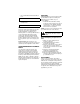
SAFETY CAUTION: POTENTIALLY HAZARDOUS SITUATION! If not avoided, MAY RESULT in minor or moderate injury. It may also be used to alert against unsafe practices. WARNING: This cutting machine is capable of amputating hands and feet and throwing objects. Failure to observe the safety instructions in the manuals and on decals could result in serious injury or death. Slopes are a major factor related to loss-of-control and tip-over accidents. Operation on all slopes requires extra caution.
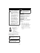
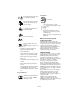
1 7 2 3 6 077541 5 4 TO AVOID SERIOUS INJURY OR DEATH POUR EVITER LES BLESSURES GRAVES OU LA MORT PARA EVITAR DANOS SERIOS O LA MUERTE Read the operator’s manual. Keep children and others away from unit while operating. Never direct discharge toward other people. Thrown objects can cause injury. Look down and behind before and while backing. Never carry children. Go up and Down slopes, not across. If machine stops going uphill, stop blade and back down slowly. Avoid sudden turns.
7. Caution! Keep children and others away from unit while operating. OL1802 OL1803 No smoking. Never direct discharge toward other people. Thrown objects can cause injury. Fill fuel tanks to 2-1/2 in. (6.35 cm) below bottom of filler neck. Look down and behind before and while backing. OL1804 OL1805 • Never fill fuel tank when engine is running, hot or unit is indoors. Never overfill fuel tank. • Replace fuel cap securely and clean up spilled fuel. Never carry children.
Keep children, people, and pets away. Be alert and shut off unit if anyone enters work area. Keep children under watchful care of a responsible adult. NEVER allow children to operate or play on or near unit. Keep area of operation clear of all toys, and debris. Thrown objects can cause injury. Stay alert for hidden hazards, holes, and ruts. Avoid uneven or rough terrain. DO NOT operate near drop-offs, ditches, or embankments.
Mow up and down slopes, not across them. Use slow speed on any slope. Tires may lose traction on slopes even though the brakes are functioning properly. Keep all movements on the slope slow and gradual. DO NOT make sudden changes in speed or direction. Use extra care while operating machines with grass catcher or other attachments. They can affect stability of the machine. Avoid starting, stopping, or turning on a slope.
A frozen battery can explode and result in death or serious injury. DO NOT charge or jump start a battery containing frozen fluid. Thaw the battery before putting on a charger or jump starting. ALWAYS keep protective structures, guards, and panels in good repair, in place and securely fastened. NEVER modify or remove safety devices. DO NOT change engine governor settings or over-speed engine. Fumes from engine exhaust can cause injury or death. DO NOT run engine in an enclosed area.
3. Adjust steering levers (see ADJUSTING STEERING LEVERS on page 20). Check function of all controls See OPERATION on page 12. Check Tire Pressure 1 3 CAUTION: Avoid injury! Explosive separation of tire and rim parts is possible when they are serviced incorrectly: • Do not attempt to mount a tire without the proper equipment and experience to perform the job. 2 3 • Do not inflate the tires above the recommended pressure. • Do not weld or heat a wheel and tire assembly.
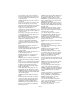
CONTROLS AND FEATURES 5 4 6 1 12 7 7 11 13 10 9 2 8 Figure 4 1. IgnitionSwitch 2. PTO Switch 3. Throttle Lever 4. Seat 5. Steering Levers 6. Parking Brake 7. Fuel Tanks 8. Mower Lift Pedal 9. Mower Deck 10. Discharge Chute 11. Fuel Gauge 12. Choke Control 13.
OPERATION Throttle Lever WARNING: AVOID INJURY. Read and understand the entire Safety section before proceeding. 1 Fast (1) – Increases engine speed. CONTROLS AND FEATURES See figure 4 for all controls and features locations. Safety Interlock System WARNING: Safety interlock failure and improper operation of unit can result in death or serious injury. Check system before each use to make sure it is functioning properly. 2 Choke Control Use to start a cold engine.
• Forward (2) – Push both steering levers forward. • Left (3) – Pull left steering lever back or push right steering lever forward or a combination of both. • Right (4) – Pull right steering lever back or push left steering lever forward or a combination of both. 1 2 3 4 02988000 Reverse (1) – Pull both steering levers backward. Press mower lift pedal and install adjustment pin in the desired adjustment hole.
STOPPING IN AN EMERGENCY STARTING AND SHUTTING OFF ENGINE Bring steering levers back to neutral, set parking brake, and turn off engine. Starting the Engine MOVING UNIT MANUALLY WARNING: DO NOT disengage or bypass transmission and coast downhill. Disengage (2) transmission bypass levers to drive unit and engage (1) transmission bypass levers to push unit manually (figure 7). NOTE: Disengage the PTO, engage the parking brake, and place the steering levers in neutral prior to starting the engine. 1.
FOR BEST PERFORMANCE Cut grass when it is dry. Keep mower blades sharp. Keep mower deck properly leveled. Adjust anti-scalp rollers to prevent scalping. Do not set height of cut too low. For very tall grass, mow twice. Do not travel too fast. Mow with the engine set at full throttle. When mulching, only remove 1/3 of grass length per cutting. Discharge clippings into areas already cut. Vary cutting pattern with each mowing. Do not allow grass or debris to collect inside of mower deck. Clean after each use.
Interval Task Follow Engine Manual Maintenance Each Use Schedule Action Perform scheduled engine maintenance. Refer to Engine Manual for detailed instructions. NOTE: To drain the oil, use the oil drain petcock (1) supplied with unit, not the drain plug that is shown in the Engine Manual. 1 Check Battery Keep battery and battery terminals clean (see Cleaning Battery and Battery Cables on page 20).
OPENING AND CLOSING HOOD REPLACING MOWER BLADE To open, pull up on the back of the hood until hood hits the hood stop and push down on back of hood to close (figure 9). Remove (Figure 11) CAUTION: Mower blades are sharp and can cut you. Wrap the blades or wear gloves, and use extra caution when servicing them. Hood tipped open. 1. Block mower blades to prevent rotation. 2. Remove mounting hardware and mower blades from mower deck. Install (Figure 11) 1.
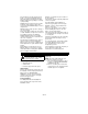
LEVELLING AND ADJUSTING PITCH OF MOWER DECK The Forward Pitch Of The Mower Blades (Figure 13): NOTE: Adjust on a level surface, with the tires inflated to the correct air pressure (see SPECIFICATIONS on page 28). There are three measurements required to level and adjust the pitch of the mower deck. 1. The distance from the mower blades to the ground. 2. The forward pitch of the mower blades. 3. The pitch of the mower blades from side-to-side. • Should be 0.0 in. (0.0 mm) to 1/4 in. (6.
Adjusting The Mower Deck To Adjust Mower Blade Height And Pitch (Figure 16): NOTE: Adjusting the mower deck will adjust the height and pitch of the mower blades. 1. Adjust the trunnions first and re-take the three measurements required to level and adjust the pitch of the mower deck. These measurements are: a. The distance from the mower blades to the ground. 1 b. The forward pitch of the mower blades. c. The pitch of the mower blades from side-to-side. 2 2.
Install (Figure 17) Charging the Battery 1. Install battery on the unit with battery hold-down bracket. 2. Connect positive (+) cable first, then negative (–) cable. 3. Apply petroleum jelly or dielectric grease to battery cable ends and terminals. 4. Tip seat back (see TIPPING SEAT FORWARD on page 16). Cleaning Battery and Battery Cables (Figure 17) 1. Tip seat forward (see TIPPING SEAT FORWARD on page 16). 2. Disconnect negative (–) cable first, then positive (+) cable. 3.
NOTE: Align handlebars by adjusting eccentric spacer until the height of handlebars are the same. NOTE: The side the unit turns toward indicates that the wheel on that side is turning slower than the other wheel. Either the wheel that is turning faster needs to slow down or the wheel that is turning slower needs to be sped up to allow the unit to travel in a straight line. 1. Determine which way the unit turns. NOTE: The forward travel adjustment bolt adjusts the rear travel of the steering lever.
3 4 4. Disconnect idler spring. 5. Remove hydrostatic belt from hydrostatic transmission pulleys, pulley, electric clutch, and idler. 5 6 Install (Figure 21) 1. Install hydrostatic belt on idler, electric clutch, pulley, and hydrostatic transmission pulleys. 2. Connect idler spring. 3. Install clutch stop. 4. Connect electric clutch connector. 5. Install PTO belt (see REPLACING PTO BELT on page 21) 2 1 7 1. 2. 3. 4. 5. 6. 7.
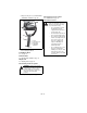
The hydraulic fluid should be at the cold fill line of the expansion tank. 2 1 3 4 1. 2. 3. 4. Drain Plug Oil Filter Filter Guard Mounting Hardware Figure 23 Purging the Hydraulic System Figure 22 Change Hydraulic Fluid and Filter NOTE: Change hydraulic fluid and filter after the first 75 hours of operation and then every 400 hours. Use 20W-50 engine oil with an SL API classification. 1. Place container under oil filter to catch oil. 2. Remove the filter guard and oil filter from the transaxle. 3.
STORAGE Short Term Storage Fuel System IMPORTANT: NEVER clean unit with highpressure water or store unit outdoors. Remove all dirt, grease, leaves, etc. Store in a clean dry area. Inspect unit for signs of wear or damage. Ensure all fasteners are properly tightened. Gasoline left in the fuel system for extended periods without a stabilizer will deteriorate, resulting in gum deposits in the system. These deposits can damage the carburetor and the fuel hoses, filter and tank.
PROBLEM Engine runs rough. PROBABLE CAUSE CORRECTION 1. Choke engaged. 1. Disengage choke. 2. Air filter cartridge plugged. 2. Clean or replace air filter cartridge. Refer to Engine Manual for detailed instructions. 3. Faulty engine. 3. Contact your Ariens Dealer. 1. The transmission bypass lever is engaged. 1. Disengage transmission bypass lever (see on page 15). 2. Faulty hydrostatic belt. 2. Replace hydrostatic belt (see REPLACING HYDROSTATIC BELT on page 22). 3. Faulty transmission. 3.
PROBLEM PROBABLE CAUSE Unit does not travel in a straight line. 1. Incorrect tire pressure. 1. Check tire pressure (see SPECIFICATIONS on page 28) 2. Steering levers need adjustment. 2. Adjust steering levers (see Forward and Reverse Speed Adjustment on page 21) 3. Hydrostatic transmission and/or linkage needs adjustment. 3. Contact your Ariens Dealer. 1. Hydrostatic transmission and/or linkage needs adjustment. 1. Contact your Ariens Dealer. 1. Mower deck not level or mower pitch is incorrect.
SERVICE PARTS ACCESSORIES Be sure to always use genuine Ariens parts to keep your unit running like new. Description See your authorized Ariens dealer to add these optional accessories to your unit. Part No. Qty Part No.
SPECIFICATIONS Model Number Model 915137 915139 2042 Zoom XL 2548 Zoom XL Engine Displacement - Kohler Courage in.3 (cc) 43 (710) Max Governed RPM 44.2 (725) 3600 + 0 3600 - 50 Speed Forward Max. - m.p.h (km/h) 7.0 (11.2) Reverse Max. - m.p.h (km/h) 3 (3.2) Turning Radius Zero Brakes Internal Transmission Electrical Starter Electric Battery 12 Volt Maintenance Free PTO (Power Take Off) Electric Clutch/Brake Fuel Fuel Type Refer to Engine Manual Fuel Tank Capacity - gal. (L) 4.
Two-Year Limited Lawn and Garden Consumer Ride-On Warranty Ariens Company (Ariens) warrants to the original purchaser that Ariens and Gravely brand consumer products manufactured and sold by Ariens after December 31, 2007 will be free from defects in material and workmanship for a period of two years after the date of purchase.
Exceptions and Limitations • Batteries are warranted only for a period of 12 months after date of purchase, on a prorated basis. For the first 90 days of the warranty period, a defective battery will be replaced free of charge. If the applicable warranty period is more than 90 days, Ariens will cover the prorated cost of any defective battery, for up to 12 months after the date of purchase.
Ariens Company 655 West Ryan Street Brillion, WI 54110-1072 920-756-2141 Fax 920-756-2407 www.ariens.