Zoom XL ® Owner/Operator Manual Models 915111 – 1842 Zoom XL 915113 – 2448 Zoom XL ENGLISH Transfer model & serial number label from product registration here.
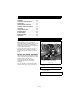
7 TABLE OF CONTENTS SAFETY . . . . . . . . . . . . . . . . . . . . . . . . . 4 ASSEMBLY. . . . . . . . . . . . . . . . . . . . . . 10 CONTROLS AND FEATURES . . . . . . . 11 OPERATION . . . . . . . . . . . . . . . . . . . . . 11 MAINTENANCE SCHEDULE . . . . . . . . 15 SERVICE AND ADJUSTMENTS . . . . . 17 STORAGE. . . . . . . . . . . . . . . . . . . . . . . 23 TROUBLESHOOTING . . . . . . . . . . . . . 24 SERVICE PARTS . . . . . . . . . . . . . . . . . 26 ACCESSORIES . . . . . . . . . . . . . . . . . .
PRODUCT REGISTRATION The Ariens dealer must register the product at the time of purchase. Registering the product will help the company process warranty claims or contact you with the latest service information. All claims meeting requirements during the limited warranty period will be honored, whether or not the product registration card is returned. Keep a proof of purchase if you do not register your unit.
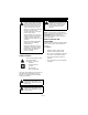
SAFETY WARNING: This cutting machine is capable of amputating hands and feet and throwing objects. Failure to observe the safety instructions in the manuals and on decals could result in serious injury or death. Slopes are a major factor related to loss-of-control and tip-over accidents. Operation on all slopes requires extra caution. Tragic accidents can occur if the operator is not alert to the presence of children. Never assume that children will remain where you last saw them.
077541 TO AVOID SERIOUS INJURY OR DEATH POUR EVITER LES BLESSURES GRAVES OU LA MORT PARA EVITAR DANOS SERIOS O LA MUERTE Read the operator’s manual. Keep children and others away from unit while operating. Never direct discharge toward other people. Thrown objects can cause injury. Look down and behind before and while backing. Never carry children. Go up and Down slopes, not across. If machine stops going uphill, stop blade and back down slowly. Avoid sudden turns.
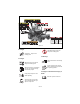
7. Caution Keep children and others away from unit while operating. OL1802 OL1803 No smoking. Never direct discharge toward other people. Thrown objects can cause injury. Fill fuel tanks to 2-1/2 in. (6.35 cm) below bottom of filler neck. Look down and behind before and while backing. OL1804 OL1805 • Never fill fuel tank when engine is running, hot or unit is indoors. Never overfill fuel tank. • Replace fuel cap securely and clean up spilled fuel. Never carry children.
Keep children, people, and pets away. Be alert and shut off unit if anyone enters work area. Keep children under watchful care of a responsible adult. NEVER allow children to operate or play on or near unit. Keep area of operation clear of all toys, and debris. Thrown objects can cause injury. Stay alert for hidden hazards, holes, and ruts. Avoid uneven or rough terrain. DO NOT operate near drop-offs, ditches, or embankments.
Mow up and down slopes, not across them. Use slow speed on any slope. Tires may lose traction on slopes even though the brakes are functioning properly. Keep all movements on the slope slow and gradual. DO NOT make sudden changes in speed or direction. Use extra care while operating machines with grass catcher or other attachments. They can affect stability of the machine. Avoid starting, stopping, or turning on a slope.
A frozen battery can explode and result in death or serious injury. DO NOT charge or jump start a battery containing frozen fluid. Thaw the battery before putting on a charger or jump starting. ALWAYS keep protective structures, guards, and panels in good repair, in place and securely fastened. NEVER modify or remove safety devices. DO NOT change engine governor settings or over-speed engine. Fumes from engine exhaust can cause injury or death. DO NOT run engine in an enclosed area.
ASSEMBLY WARNING: AVOID INJURY. Read and understand the entire Safety section before proceeding. Check function of all controls See OPERATION on page 11. . 1 3 Tools Required • Adjustable wrench • Petroleum jelly or dielectric grease. Unpack Unit 2 Remove unit and all other components from the shipping container. Engage transmission bypass lever (see MOVING UNIT MANUALLY on page 14). Push unit from container onto a level surface. Disengage transmission bypass lever.
CONTROLS AND FEATURES 5 4 6 1 12 7 7 11 13 10 9 3 2 8 Figure 4 1. Ignition Switch 2. PTO Switch 3. Throttle Lever 4. Seat 5. Steering Levers 6. Parking Brake 7. Fuel Tanks 8. Mower Lift Pedal 9. Mower Deck 10. Discharge Chute 11. Fuel Shut-Off Valve 12. Choke Control 13. Hour meter OPERATION WARNING: AVOID INJURY. Read and understand the entire Safety section before proceeding.
Test Steering PTO Lever Parking Brake Engine 4*+ Out of Neutral Position Off Disengaged Shuts Off 5*+ Neutral Position On Engaged Shuts Off Throttle Lever (915113) 1 Fast (1) – Increases engine speed. * Test with engine running. + Operator lifts off seat. Ignition Switch 1 2 3 4 Operate ignition switch with a removable key. Ignition switch has four positions: Stop (1), Headlight (2), Run (3), Start (4).
Left (3) – Pull left steering lever back or push right steering lever forward or a combination of both. • Right (4) – Pull right steering lever back or push left steering lever forward or a combination of both. 1 2 3 4 NOTE: Adjusting the seat further forward will help increase the leverage in lifting the mower deck (see FILLING FUEL TANKS on page 13). NOTE: The unit comes shipped with the front axle in the lockout position.
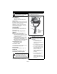
MOVING UNIT MANUALLY STARTING AND SHUTTING OFF ENGINE WARNING: DO NOT disengage or bypass transmission and coast downhill. Starting the Engine Disengage (2) transmission bypass levers to drive unit and engage (1) transmission bypass levers to push unit manually (figure 7). NOTE: Disengage the PTO, engage the parking brake, and place the steering levers in neutral prior to starting the engine. 1. If the engine is cold, move the choke control to the On position.
OPERATING MOWER FOR BEST PERFORMANCE 1. Start engine. 2. Set throttle lever to fast. IMPORTANT: Never engage PTO if mower is plugged with grass or other material. 3. Engage PTO to start mower blades. NOTE: The parking brake must be disengaged prior to moving the steering levers from the neutral lockout position. 4. Release parking brake. 5. Use steering levers to move the unit. 6. Disengage PTO to stop mower blades. Cut grass when it is dry. Keep mower blades sharp. Keep mower deck properly leveled.
. Interval Task Action Check Safety Interlock System Check Parking Brake WARNING: Safety interlock system failure and improper operation of unit can result in death or serious injury. Test this system each time the unit is operated. If this system does not function as described, do not operate until repairs are made (see Safety Interlock System on page 11). Engage parking brake and engage transmission bypass lever (see MOVING UNIT MANUALLY on page 14). Push unit.
Interval Task Action Check Battery Keep battery and battery terminals clean (see Cleaning Battery and Battery Cables on page 20). Lubricate Unit Apply grease to zerk (1) on each front wheel 25 Hours or Every Season 1 50 Hours Check or Every Fasteners Season Check mower blade mounting hardware and all other fasteners. Replace fasteners that are missing or damaged. Tighten all nuts and bolts to the correct torque value. Check All 100 Belts Hours or Every Season Replace worn or deteriorated belts.
. 1 2 2 3 5 4 6 1 1. Rear Trunnion 2. PTO Belt 3. Mower Deck 4. Drag Link 1. Adjustment Pin 2. Deck Access plate Figure 10 REPLACING MOWER BLADE 5. Front Trunnion 6. Lift Arm Figure 12 Remove (Figure 11) CAUTION: Mower blades are sharp and can cut you. Wrap the blades or wear gloves, and use extra caution when servicing them. 1. Block mower blades to prevent rotation. 2. Remove mounting hardware and mower blades from mower deck. Install (Figure 11) 1.
The Pitch Of The Mower Blades From Side-To-Side (Figure 15): Lowest Cutting Position 3 1 • 2 Should be within 1/4 in. (6.35 mm) as measured on each side of the mower deck. NOTE: This measurement must be taken when the mower blades ends are perpendicular (at a right angle) to the frame of the unit. Side-To-Side Pitch 1-1/2 in. + 1/4 in. (3.8 cm + 0.64 cm) 3 1 2 Highest Cutting Position 3 1 2 1/4-in. (6.35 cm) from Side-To-Side 1. Mower Deck 2. Mower Blade 3. Ground 4-1/2 in. + 1/4 in. (11.
3. Apply petroleum jelly or dielectric grease to battery cable ends and terminals. 4. Tip seat back (see TIPPING SEAT FORWARD on page 17). Cleaning Battery and Battery Cables (Figure 17) 1 1. Tip seat forward (see TIPPING SEAT FORWARD on page 17). 2. Disconnect negative (–) cable first, then positive (+) cable. 3. Clean battery cable ends, negative (–) terminal, and positive (+) terminal with a wire brush and rinse with a weak baking soda solution. 4.
Charging the Battery NOTE: Align handlebars by adjusting eccentric spacer until the height of handlebars are the same. (Figure 17) WARNING: FROZEN BATTERIES CAN EXPLODE and result in death or serious injury. DO NOT charge a frozen battery. Let the battery thaw before charging. 1 Follow First Aid directions for contact with battery fluid. • External Contact: Flush with water.
NOTE: The side the unit turns toward indicates that the wheel on that side is turning slower than the other wheel. Either the wheel that is turning faster needs to slow down or the wheel that is turning slower needs to be sped up to allow the unit to travel in a straight line. 1. Determine which way the unit turns. NOTE: The forward travel adjustment bolt adjusts the rear travel of the steering lever. The rear travel adjustment bolt adjusts the forward travel of the steering lever. 2.
Install (Figure 21) 1 1. Install hydrostatic belt on idler, electric clutch, pulley, and hydrostatic transmission pulleys. 2. Connect idler spring. 3. Install clutch stop. 4. Connect electric clutch connector. 5. Install PTO belt (see REPLACING PTO BELT on page 22) 2 6 2 4 1. 2. 3. 4. 5. 6.
TROUBLESHOOTING PROBLEM PROBABLE CAUSE Engine will not crank/start. 1. Safety interlock system is not engaged or is faulty. 1. Check safety interlock system (see Safety Interlock System on page 11). 2. Fuel tanks empty. 2. Fill fuel tanks (see FILLING FUEL TANKS on page 13). 3. Discharged battery. 3. Charge battery (see Charging the Battery on page 21). 4. Poor connection between battery and battery cables. 4.
PROBLEM PROBABLE CAUSE PTO or mower blades do not engage or shuts off. 1. Operator presence switch not depressed. 1. Depress operator presence switch by sitting on seat. 2. Faulty operator presence switch. 2. Contact your Ariens Dealer. 3. Electric clutch connector is loose or disconnected. 3. Connect the electric clutch connector. See REPLACING HYDROSTATIC BELT on page 22 for the electric clutch connector location. 4. Faulty PTO belt. 4. Replace PTO belt (see REPLACING PTO BELT on page 22). 5.
PROBLEM Poor cutting quality. PROBABLE CAUSE CORRECTION 1. Mower deck not level or mower pitch is incorrect. 2. Level and adjust pitch of mower deck (see The Distance From The Mower Blades To The Ground (Figure 13): on page 18). 2. Dull or faulty mower blades. 3. Sharpen mower blades or replace mower blades (see REPLACING MOWER BLADE on page 18). SERVICE PARTS Be sure to always use genuine Ariens parts to keep your unit running like new. Part No.
SPECIFICATIONS Model Number 915111 915113 1842 2448 Model Engine Type Engine Power Max - HP (kW) at Governed RPM Briggs and Stratton ELS Twin 18 (13.4) 24 (17.8) 3600 3600 Max Governed RPM Speed Forward Max. - m.p.h (km/h) 7.0 (11.2) Reverse Max. - m.p.h (km/h) 3 (3.2) Turning Radius Zero Brakes Internal Transmission Electrical Starter Electric Battery 12 Volt Maintenance Free PTO (Power Take Off) Electric Clutch/Brake Fuel Fuel Type Refer to Engine Manual Fuel Tank Capacity - gal.
SPECIFICATIONS Model Number 915111 915113 1842 2448 Model Rear Tire Pressure - psi (kPa) 10 (69) Mower Deck Cutting Height - in. (cm) Cutting Width - in. (cm) 1-1/2 - 4-1/2 (3.81 - 11.4) 42 (107) 48 (122) Max. Towing Capacity - lbs (kg) 300 (136) Max. Tongue Weight - lbs (kg) 30 (13.
Ariens Limited Warranties 2-Year Limited Lawn and Garden Consumer Warranty Ariens Company (Ariens) warrants to the original purchaser that Ariens and Gravely brand consumer products manufactured by Ariens Company will be free from defects in material and workmanship for a period of two (2) years after the date of purchase, and that Ariens will repair any defect in material or workmanship, and repair or replace any defective part, subject to the conditions, limitations and exclusions set forth herein.
Exceptions, Limitations, Exclusions These warranties are subject to the following conditions, limitations, and exclusions: The following items are excluded from this To obtain warranty service, the following warranty: conditions must be met: • Engines and entry and are not covered by this • The purchaser must perform the warranty. maintenance and minor adjustments • Hydro-Gear transmissions and/or explained in the owner’s manual.
Ariens Company • 655 W. Ryan St, P.O. Box 157 • Brillion, WI 54110-0157• (920) 756-2141 • www.ariens.
Ariens Company 655 West Ryan Street Brillion, WI 54110-1072 920-756-2141 Fax 920-756-2407 www.ariens.