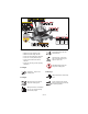
Zoom XL ® Owner/Operator Manual Manuel Du Propriétaire/Utilisateur Models 915163 – Zoom XL 42 915165 – Zoom XL 48 915167 – Zoom XL 54 ENGLISH FRANÇAIS ENGLISH 04043500 10/10 Printed in USA
TABLE OF CONTENTS SAFETY. . . . . . . . . . . . . . . . . . . . . . . . . . 4 STORAGE . . . . . . . . . . . . . . . . . . . . . . . 27 ASSEMBLY . . . . . . . . . . . . . . . . . . . . . . 10 TROUBLESHOOTING . . . . . . . . . . . . . 27 CONTROLS AND FEATURES . . . . . . . 12 SERVICE PARTS . . . . . . . . . . . . . . . . . 29 OPERATION . . . . . . . . . . . . . . . . . . . . . 13 ACCESSORIES. . . . . . . . . . . . . . . . . . . 29 MAINTENANCE SCHEDULE . . . . . . . . 17 SPECIFICATIONS . . . . . . . .
2 DELIVERY 1 Customer Note: If you have purchased this product without complete assembly and instruction by your retailer, it is your responsibility to: • Read and understand all assembly instructions in this manual. If you do not understand or have difficulty following the instructions, contact your nearest Ariens Dealer for assistance. NOTE: To locate your nearest Ariens Dealer, go to www.ariens.com on the internet. NOTE: 1. Unit Serial Number Label 2.
SAFETY WARNING: This cutting machine is capable of amputating hands and feet and throwing objects. Failure to observe the safety instructions in the manuals and on decals could result in serious injury or death. Slopes are a major factor related to loss-of-control and tip-over accidents. Operation on all slopes requires extra caution. Tragic accidents can occur if the operator is not alert to the presence of children. Never assume that children will remain where you last saw them.
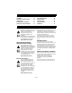
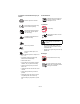
1 7 2 MAX. FILL 3 04237000 6 077541 8 5 4 TO AVOID SERIOUS INJURY OR DEATH POUR EVITER LES BLESSURES GRAVES OU LA MORT PARA EVITAR DANOS SERIOS O LA MUERTE Read the operator’s manual. Keep children and others away from unit while operating. Never direct discharge toward other people. Thrown objects can cause injury. Look down and behind before and while backing. Never carry children. Go up and Down slopes, not across. If machine stops going uphill, stop blade and back down slowly.
5. Danger! To Avoid Serious Injury or Death 6. Hot Surfaces! Read the operator’s manual. OL1801 OL1801 DO NOT touch parts which are hot from operation. ALWAYS allow parts to cool. 7. Caution! Keep children and others away from unit while operating. OL1802 No smoking. OL1803 Never direct discharge toward other people. Thrown objects can cause injury. MAX. FILL Fill fuel tank to bottom of neck MAXIMUM. Look down and behind before and while backing.
EMISSION CONTROL SYSTEM This equipment and/or its engine may include exhaust and evaporative emissions control system components required to meet U.S. Environmental Protection Agency (EPA) and/or California Air Resources Board (CARB) regulations. Tampering with emission controls and components by unauthorized personnel may result in severe fines or penalties. Emission controls and components can only be adjusted by an Ariens Company dealer or an authorized engine manufacturer's service center.
DO NOT operate unit if safety interlock system is damaged or disabled. Check safety interlock before each use. ALWAYS remove key to prevent unauthorized use. DO NOT operate at too fast a rate. Slow down before turning. Stop engine before removing grass catcher or unclogging chute. DO NOT mow on wet grass. Reduced traction could cause sliding. DO NOT mow with the deck access plate open. Always make sure the access plate is down, or secured down, with the hardware.
Replace fuel cap securely and clean up spilled fuel. NEVER fill containers inside a vehicle or on a truck or trailer bed with a plastic liner. Always place containers on the ground away from your vehicle before filling. When practical, remove gas-powered equipment from the truck or trailer and refuel it on the ground. If this is not possible, then refuel such equipment on a trailer with a portable container, rather than from a gasoline dispenser nozzle.
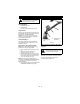
ASSEMBLY WARNING: AVOID INJURY. Read and understand the entire Safety section before proceeding. Tools Required • Adjustable wrench • 9/16" wrench • Petroleum jelly or dielectric grease. 1 Unpack Unit Remove unit and all other components from the shipping container. Engage transmission bypass lever (see MOVING UNIT MANUALLY on page 16). Push unit from container onto a level surface. Disengage transmission bypass lever.
Discharge Chute in Transport Position Check Safety Interlock System WARNING: Safety interlock failure and improper operation of unit can result in death or serious injury. Check system before each use to make sure it is functioning properly. See Safety Interlock System on page 13. Check function of all controls See OPERATION on page 13.
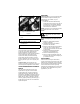
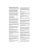
CONTROLS AND FEATURES 4 6 5 2 13 12 7 11 1 8 10 9 1. Ignition Switch 2. PTO Switch 3. Throttle Lever 4. Seat 5. Steering Levers 6. Parking Brake 7. Fuel Tank Figure 5 8. Mower Lift Pedal 9. Mower Deck 10. Discharge Chute 11. Fuel Gauge 12. Choke Control 13.
OPERATION Throttle Lever WARNING: AVOID INJURY. Read and understand the entire Safety section before proceeding. 1 Fast (1) – Increases engine speed. CONTROLS AND FEATURES See figure 5 for all controls and features locations. Safety Interlock System WARNING: Safety interlock failure and improper operation of unit can result in death or serious injury. Check system before each use to make sure it is functioning properly.
Timer (TMR1): measures the time spent on individual jobs. Press and hold the toggle button to reset the timer to zero. TMR1 will then start measuring engine run time until it is reset to zero again. Service Alert (Chg Oil, Chg H Oil & Filter, SVC Airfilter): reminds operators of the maintenance interval for changing the engine oil, changing the hydraulic oil and filter and servicing the air filter. The alert starts counting down two hours before the maintenance is due.
Adjusting Seat GASOLINE Lift adjustment lever and slide seat forward or backward to the desired position. IMPORTANT: ALWAYS use gasoline that meets the following guidelines: • Clean, fresh gasoline. • A minimum of 87 octane/87 AKI (91 RON). High altitude use may require a different octane. Consult your engine manual. • Gasoline with up to 10% ethanol (gasohol) or up to 10% MTBE (methyl tertiary butyl ether) is acceptable.
MOVING UNIT MANUALLY WARNING: DO NOT disengage or bypass transmission and coast downhill. Disengage (2) transmission bypass levers to drive unit and engage (1) transmission bypass levers to push unit manually (figure 8). 3. Turn ignition key to start position and release once the engine has started. 4. Pull the choke lever toward operator position when the engine is warm. Wait until the engine is running smoothly before operation.
MAINTENANCE SCHEDULE WARNING: AVOID INJURY. Read and understand the entire Safety section before proceeding. NOTE: To have full access to the engine, the seat must be tipped forward (see TIPPING SEAT FORWARD on page 18) and the hood opened (see OPENING AND CLOSING HOOD on page 19). IMPORTANT: Proper maintenance can prolong the life of unit. The following chart shows the recommended service schedule. Refer to the maintenance instructions in the Engine Manual for additional information.
Interval Task Follow Engine Manual MaintenEach Use ance Schedule Action Perform scheduled engine maintenance. Refer to Engine Manual for detailed instructions. NOTE: To drain the oil, use the oil drain hose (1) supplied with unit, not the drain plug that is shown in the Engine Manual. 1 Check Battery Keep battery and battery terminals clean (see Cleaning Battery and Battery Cables on page 22).
OPENING AND CLOSING HOOD REPLACING MOWER BLADE To open, pull up on the back of the hood until hood hits the hood stop and push down on back of hood to close (figure 10). Remove (Figure 12) CAUTION: Mower blades are sharp and can cut you. Wrap the blades or wear gloves, and use extra caution when servicing them. Hood tipped open. 1. Block mower blades to prevent rotation. 2. Remove mounting hardware and mower blades from mower deck. Install (Figure 12) 1.
LEVELLING AND ADJUSTING PITCH OF MOWER DECK The Forward Pitch Of The Mower Blades (Figure 14): NOTE: Adjust on a level surface, with the tires inflated to the correct air pressure (see SPECIFICATIONS on page 30). There are three measurements required to level and adjust the pitch of the mower deck. 1. The distance from the mower blades to the ground. 2. The forward pitch of the mower blades. 3. The pitch of the mower blades from side-to-side. • Should be 0.0 in. (0.0 mm) to 1/4 in. (6.
Adjusting The Mower Deck To Adjust Mower Blade Height And Pitch (Figure 17): NOTE: Adjusting the mower deck will adjust the height and pitch of the mower blades. 1. Adjust the trunnions first and re-take the three measurements required to level and adjust the pitch of the mower deck. These measurements are: a. The distance from the mower blades to the ground. 1 b. The forward pitch of the mower blades. 2 c. The pitch of the mower blades from side-to-side. 2.
SERVICING BATTERY Install (Figure 19) 1. Install battery on the unit with battery hold-down bracket. 2. Connect positive (+) cable first, then negative (–) cable. 3. Apply petroleum jelly or dielectric grease to battery cable ends and terminals. 4. Tip seat back (see TIPPING SEAT FORWARD on page 18). NOTE: Unit comes equipped with a maintenance-free battery that requires no regular maintenance except cleaning the terminals and periodic charging.
Charging the Battery ADJUSTING STEERING LEVERS (Figure 19) (Figure 20) WARNING: FROZEN BATTERIES CAN EXPLODE and result in death or serious injury. DO NOT charge a frozen battery. Let the battery thaw before charging. Adjustment 3 Adjustment 1 3 1 Follow First Aid directions for contact with battery fluid. • External Contact: Flush with water. • Eyes: Flush with water for at least 15 minutes and get medical attention immediately! • Internal Contact: Drink large quantities of water.
• Rotate this end away from the the operator position to move the steering levers in. Turning adjustment bolt counter clockwise to increase steering lever travel. Rotate this end away from the operator position to move the steering levers out. Figure 21 2 3. Adjust Steering Lever Forward or Backward 1. Loosen, do not remove, the bolts securing the handlebar to the upper control arm. 2. Slide steering lever forward or backward to desired position and tighten bolts. NOTE: Tigthen upper bolt first.
3 4 Install (Figure 24) 5 1. Install hydrostatic belt on idler, electric clutch, pulley, and hydrostatic transmission pulleys. 2. Connect idler spring. 3. Install clutch stop. 4. Connect electric clutch connector. 5. Install PTO belt (see REPLACING PTO BELT on page 24). 6 2 1 1 1. 2. 3. 4. 5. 6. 7. Idler Spring Electric Clutch PTO Belt Idler Hole Idler Pulley Idler Arm Belt Cover 2 6 7 3 2 Figure 23 4 4. Remove PTO belt from left mower deck pulley. 5.
1 The hydraulic fluid should be at the cold fill line of the expansion tank. 2 3 4 1. 2. 3. 4. Drain Plug Oil Filter Filter Guard Mounting Hardware Figure 26 Purging the Hydraulic System Figure 25 Change Hydraulic Fluid and Filter (Figure 26) NOTE: Change hydraulic fluid and filter after the first 75 hours of operation and then every 400 hours. Use 20W-50 engine oil with an SL API classification. 1. Place container under oil filter to catch oil. 2.
STORAGE Short Term Storage Fuel System IMPORTANT: NEVER clean unit with highpressure water or store unit outdoors. Remove all dirt, grease, leaves, etc. Store in a clean dry area. Inspect unit for signs of wear or damage. Ensure all fasteners are properly tightened. Gasoline left in the fuel system for extended periods without a stabilizer will deteriorate, resulting in gum deposits in the system. These deposits can damage the carburetor and the fuel hoses, filter and tank.
PROBLEM Engine runs rough. PROBABLE CAUSE CORRECTION 1. Choke engaged. 1. Disengage choke. 2. Air filter cartridge plugged. 2. Clean or replace air filter cartridge. Refer to Engine Manual for detailed instructions. 3. Faulty engine. 3. Contact your Ariens Dealer. 1. The transmission bypass lever is engaged. 1. Disengage transmission bypass lever (see on page 17). 2. Faulty hydrostatic belt. 2. Replace hydrostatic belt (see REPLACING HYDROSTATIC BELT on page 25). 3. Faulty transmission. 3.
PROBLEM PROBABLE CAUSE Unit does not travel in a straight line. CORRECTION 1. Incorrect tire pressure. 1. Check tire pressure (see SPECIFICATIONS on page 30) 2. Steering levers need adjustment. 2. Adjust steering levers (see Forward and Reverse Speed Adjustment on page 24) 3. Hydrostatic transmission and/or linkage needs adjustment. 3. Contact your Ariens Dealer. Unit creeps with steering levers in neutral position. 1. Hydrostatic transmission and/or linkage needs adjustment. 1.
SPECIFICATIONS Model Number 915163 915165 915167 Model Zoom XL 42 Zoom XL 48 Zoom XL 54 Engine Kawasaki FR651 Kawasaki FR691 Displacement - in.3 (cc) 45.5 (746) Max Governed RPM (May be different from maximum RPM) 3600 + 0 3600 – 50 Speed Forward Max. - m.p.h (km/h) 6.5 (10.46) Reverse Max. - m.p.h (km/h) 3 (3.
CALIFORNIA AND EPA (UNITED STATES ENVIRONMENTAL PROTECTION AGENCY) EVAPORATIVE EMISSION CONTROL WARRANTY STATEMENT YOUR WARRANTY RIGHTS AND OBLIGATIONS The CARB (California Air Resources Board), the EPA, and Ariens Company are pleased to explain the evaporative emission control system's warranty on your 2011 model year small off-road equipment. In California, new equipment that uses small off-road engines must be designed, built, and equipped to meet the State's stringent anti-smog standards.
(4.) (5.) (6.) (7.) (8.) (9.) Repair or replacement of any warranted part under the warranty provisions of this article must be performed at no charge to the owner at an authorized Ariens, Gravely, or Parker service representative. Notwithstanding the provisions of subsection (4) above, warranty services or repairs must be provided at authorized Ariens, Gravely, or Parker service representatives that are franchised to service the subject small off-road equipment.
Two-Year Limited Lawn and Garden Consumer Ride-On Warranty Ariens Company (Ariens) warrants to the original purchaser that Ariens, Gravely and Countax brand consumer products manufactured and sold by Ariens will be free from defects in material and workmanship for a period of two years after the date of purchase.
To find an Ariens or Gravely authorized service representative, contact Ariens at: 655 W. Ryan Street Brillion, WI 54110 (920) 756 - 4688 www.ariens.com www.gravely.com To find a Countax authorized service representative, contact Countax at: Countax Ltd Countax House Great Haseley Oxfordshire OX44 7PF 0800 597 7777 www.countax.com Exceptions and Limitations • Batteries are warranted only for a period of 12 months after date of purchase, on a prorated basis.
Ariens Company 655 West Ryan Street Brillion, WI 54110-1072 920-756-4688 Fax 920-756-2407 www.ariens.