MAX ZOOM™ Owner/Operator Manual Models 991056 – Max Zoom 2560 991065 – Max Zoom 2552 ENGLISH FRANÇAIS ESPAÑOL 03790900 11/08 Printed in USA
TABLE OF CONTENTS Safety . . . . . . . . . . . . . . . . . . . . . . . . . . . 3 Storage . . . . . . . . . . . . . . . . . . . . . . . . . 27 Assembly . . . . . . . . . . . . . . . . . . . . . . . . 8 Accessories . . . . . . . . . . . . . . . . . . . . . 28 Controls and Features . . . . . . . . . . . . 10 Service Parts . . . . . . . . . . . . . . . . . . . . 28 Operation . . . . . . . . . . . . . . . . . . . . . . . 11 Specifications . . . . . . . . . . . . . . . . . . . 29 Maintenance Schedule . .
DISCLAIMER Ariens reserves the right to discontinue, change, and improve its products at any time without public notice or obligation to the purchaser. The descriptions and specifications contained in this manual were in effect at printing. Equipment described within this manual may be optional. Some illustrations may not be applicable to your unit. DEALER DELIVERY Dealer should: 1.
PRACTICES AND LAWS WARNING: POTENTIALLY HAZARDOUS SITUATION! If not avoided, COULD RESULT in death or serious injury. Practice usual and customary safe working precautions, for the benefit of yourself and others. Understand and follow all safety messages. Be alert to unsafe conditions and the possibility of minor, moderate, or serious injury or death. Learn applicable rules and laws in your area, including those that may restrict the age of the operator.
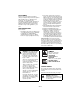
Keep children out of work area and under watchful care of a responsible adult. OL4470 3. WARNING! Do not operate mower unless guards are in operating position or bagger is attached. Always stand clear of discharge area. NEVER CARRY CHILDREN. OL4430 Do not operate mower unless bagger is attached or guards are in operating position. OL4480 Go up and down slopes, not across. DO NOT operate on slopes over 10°. OL3320 4.
ALWAYS check overhead and side clearances carefully before operation. ALWAYS be aware of traffic when operating along streets or curbs. Keep children and people away. Keep children out of work area and under watchful care of a responsible adult. Keep area of operation clear of all toys, pets, and debris. Thrown objects can cause injury. Check for weak spots on docks, ramps or floors. Avoid uneven work areas and rough terrain. Stay alert for hidden hazards or traffic.
Never direct discharge towards persons or property that may be injured or damaged by thrown objects. Use extreme caution on gravel surfaces. Always stand clear of the discharge area. ALWAYS disengage PTO, stop unit and engine, remove key, engage parking brake and allow moving parts to stop before leaving operator’s position. Never engage PTO while raising attachment or when attachment is in raised position. DO NOT operate at too fast a rate. DO NOT change engine governor settings or overspeed engine.
When practical, remove gas-powered equipment from the truck or trailer and refuel it on the ground. If this is not possible, then refuel such equipment on a trailer with a portable container, rather than from a gasoline dispenser nozzle. Keep the nozzle in contact with the rim of the fuel tank or container opening at all times until fueling is complete. Do not use a nozzle lockopen device. If fuel is spilled on clothing, change clothing immediately. Avoid Electric Shock.
3. Tires - See Specifications on page 29. 8. Fill Engine Fuel Tank - Add clean fuel to the fuel tank. IMPORTANT: Refer to Engine Manual for fuel type. 9. Hardware - Check for loose hardware. 10. Check Safety Interlock System - Check to see that the interlock system operates correctly (See Safety Interlock System on page 11).
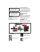
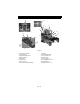
CONTROLS AND FEATURES 16 10 15 2 3 1 9 4 11 7 14 6 8 12 OF4035 OF4095 OM4090 OM4085 5 Figure 4 1. Fuel Tanks and Caps 2. Steering Levers 3. Hydraulic Oil Reservoir 4. Ignition Switch 5. Hour Meter 6. Throttle Lever 7. Choke Control 8. Power Take Off (PTO) Switch 13 9. Battery 10. Fuel Shut Off Valve 11. Mower Lift Pedal 12. Mower Deck 13. Mower Lift Lock 14. Seat Adjustment Lever 15. Parking Brake 16.
OPERATION Steering Levers WARNING: AVOID INJURY. Read and understand entire Safety section before proceeding. A B C D CONTROLS AND FEATURES See Figure 4 for Controls and Features locations. 07757600B Safety Interlock System WARNING: Safety interlock system failure and improper operation of unit can result in death or serious injury. Test this system each time the unit is operated. If this system does not function as described, do not operate until repairs are made.
Choke Control OF1680 Mower Lift Pedal Push the choke lever forward to start a cold engine. Pull the choke lever to the rear when the engine gets warm. Throttle Lever The throttle lever changes the engine speed. Move the throttle lever to Fast (1) to increase engine speed. Move the lever to Slow (2) to decrease engine speed. 1 OF1700 Mower lift pedal raises and lowers mower deck for mowing or transport. Transport: Push mower lift pedal all the way forward until lift lock engages.
Hour Meter 4. Check Tire Pressure Records total number of hours the engine has been run. See Specifications on page 29 for correct tire pressure. 5. Check Hydraulic Fluid Level IMPORTANT: Keep a record of Hour Meter readings for recommended Lubrication and Maintenance intervals. NOTE: For accurate readings be sure Ignition Switch is OFF when unit is not in operation. FILLING FUEL TANK See Check Hydraulic Fluid Level on page 17. 6.
TO MOW WITH UNIT 6. Engage parking brake. 7. Push the right and left bypass levers to the drive position. Operate the unit only when seated in the operator’s position. 1. Start the engine. Let the engine warm until it is running smoothly. 2. Release parking brake. WARNING: Move the steering control levers slowly and keep the throttle control lever at slow speed until you learn how to operate the unit. 3. Bring the steering levers to neutral. 4. Slow the engine down to about 3/4 speed. 5.
FOR BEST PERFORMANCE Mow with the engine set at full throttle. When mulching, only remove 1/3 of grass length per cutting. Do not cut more than 1 inch (2.54 cm) at any one time. Discharge clippings into areas already cut. Vary cutting pattern with each mowing. Do not allow grass or debris to collect inside of mower deck. Clean after each use. Cut grass when it is dry. Keep mower blades sharp. Keep mower deck properly levelled. Adjust anti-scalp rollers to prevent scalping.
Period Service Task Each Use Follow Engine Manual Maintenance Schedule Perform scheduled engine maintenance. Refer to engine manual for detailed instructions. Every 25 Hours Check Mower Blades Check mower blades for wear. Sharpen or replace as needed. See Mower Blades on page 18. Check Air FIlter Check air filter for dirt. Clean as required. Follow Engine Manual for maintenance schedule. Lubricate Unit Oil all pivot points and pin connections. Grease lube fittings. See Lubricate Unit on page 21.
Check Hydraulic Fluid Level 2 1 Check the system with the unit cold and parked on a flat, level surface. Then run the unit for about one minute and recheck the levels. 2 To Add Hydraulic Fluid: 3 1. Remove the cap from the expansion tank. 2. Fill the expansion tank with 20W-50 engine oil with an SL API classification until oil level reaches the cold fill line on the tank. 3. Install the expansion tank cap and then purge the system. See Purging the Hydraulic System on page 18. OF4310 4 1.
6. Install the filter guards removed in step 2. Tighten the mounting screws to 65 lbf-in (7.3 N•m). 7. Fill with 20W-50 engine oil with an SL API classification until oil appears at the bottom of the drain plug (about 2 quarts per transaxle). Install the drain plug and tighten it to 180 lbf-in (20.3 N•m). 8. Repeat steps 1–7 for the other transaxle. 9. Follow the instructions in To Add Hydraulic Fluid: on page 17. 2 1 4. Stop the engine and put the transaxle bypass levers in the drive position.
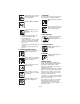
4. Install mower blade(s) on unit. 5. Tighten the bolts to a torque of 115-125 lbf-ft (156-169.5 N•m). DO NOT Sharpen to This Pattern 2 1 1 2 3 DISCARD if More Than 1/2 in. (1.27 cm) 4 1 1. Blade 2. Cup Washer 3. Bolt Figure 9 3 Sharpen the Mower Blades OT0792 4 Sharpen to This Pattern CAUTION: DO NOT sharpen mower blades while on unit. An unbalanced mower blade will cause excessive vibration and eventual damage to unit. Check mower blade balance before reinstalling blades.
Unit comes equipped with a maintenancefree battery that requires no regular maintenance except cleaning the terminals. Remove Battery 1. Shut OFF engine. Engage parking brake. Remove the ignition key. 2. Place seat in the service position (See Maintenance Schedule on page 15). 3. Disconnect cables from battery (negative, then positive) (Figure 11). 4. Remove hold down and remove battery. Replace Battery 1. Replace battery and secure with battery hold down. 2.
LUBRICATE UNIT 7. If a wheel moves, adjust the return to neutral mechanism on the hydraulic pump: a. Loosen the return to neutral screw on the pump. b. Slowly move the speed and direction control bracket clockwise or counterclockwise until the wheel stops moving. c. Hold the stop bracket in position and tighten the return to neutral screw on the pump. 8. Move steering levers from Forward to Reverse several times and return steering levers to neutral position. Check wheel(s) for movement. 9.
2 3 3 2 1 1 1 2 4 1. Limiter Bolt 4. Stop Bracket 2. Jam Nut 3. Steering Lever Figure 15 4 ADJUSTING THE HEIGHT OF THE STEERING LEVER HANDLES 5 1 1. Tie-Rod Jam Nut 2. Tie-Rod 3. Steering Lever NOTE: Align handlebars by adjusting eccentric spacer until the height of handlebars are the same. 1. Remove mounting hardware and move handlebar up or down until the steering levers are at the appropriate height. 2. Install mounting hardware. 4. Brake Interlock 5.
ADJUSTING THE PARKING BRAKE PTO BELT The parking brake should not need adjustment, however if the parking brake does not hold the unit properly, the brake may need adjustment. WARNING: MOVING PARTS can cut or amputate body parts. ALWAYS wait for moving parts to stop before performing maintenance or service. Check Adjustment NOTE: Be sure to check the parking brake on both sides of the unit (Figure 17). 1. Engage parking brake and set both transmission bypass valves to the neutral position.
1. Slowly release the tension on the long mower belt idler until all the tension is removed from the springs. 2. Remove long mower belt from left blade spindle and remove from deck. 3. Slowly release the tension on the short belt idler until all the tension is removed from the springs. 4. Remove short mower belt from right blade spindle and from deck. Idler pivot bolt must be loosened slightly to gain clearance to remove belt from under idler pulley (Figure 19). 5.
MOWER DECKS Push the mower lift pedal forward between cutting height number 4 and number 5 to align the holes in the deck lift shaft and the deck lift cover. Insert the cutting height pin in the holes on the side of the deck lift cover so it passes all the way through the deck lift cover and shaft. Anti-scalp Roller Adjustment The anti-scalp rollers are set at the factory for typical mowing height, but can be adjusted for high or low cutting conditions (Figure 21).
Installing the Mower Deck (Figure 22) 1. Slide mower deck under unit. 2. Connect mower mounting arms to deck with mower mounting pins. 3. Install link chains on the mower lift arms in the same holes they were removed from. 4. Install PTO mower belt (See Replacing Mower Belts on page 23). 5. Level mower deck (See Leveling the Mower Deck on page 26). NOTE: Pitching the front of the blades lower than the rear provides a balance between cut quality and the power needed to cut grass.
Fuel System Height Adjusters Gasoline left in the fuel system for extended periods without a stabilizer will deteriorate, resulting in gum deposits in the system. These deposits can damage the carburetor and the fuel hoses, filter and tank. Prevent deposits from forming in the fuel system during storage by adding a quality fuel stabilizer to the fuel. Follow the recommended mix ratio found on the fuel stabilizer container. To treat the fuel system for storage: 1.
ACCESSORIES SERVICE PARTS Part No. Description Part No.
SPECIFICATIONS Model Number 991056 991065 Model Max Zoom 2560 Max Zoom 2552 Engine Kohler Kohler Engine Model Number Engine Displacement - in3 (cc) Courage Courage 44.2 (725.0) 44.2 (725.0) Governed RPM (May be different from maximum RPM) 3600 ± 75 Liquid or Air Cooled Air Speed Forward Maximum – mph (km/h) 8.0 (12.9) Reverse Maximum – mph (km/h) 4.0 (6.
Two-Year Limited Lawn and Garden Consumer Ride-On Warranty Ariens Company (Ariens) warrants to the original purchaser that Ariens and Gravely brand consumer products manufactured and sold by Ariens after December 31, 2007 will be free from defects in material and workmanship for a period of two years after the date of purchase.
Exceptions and Limitations • Batteries are warranted only for a period of 12 months after date of purchase, on a prorated basis. For the first 90 days of the warranty period, a defective battery will be replaced free of charge. If the applicable warranty period is more than 90 days, Ariens will cover the prorated cost of any defective battery, for up to 12 months after the date of purchase.
Ariens Company 655 West Ryan Street Brillion, WI 54110-1072 920-756-2141 Fax 920-756-2407 www.ariens.com WARNING The engine exhaust from this product contains chemicals known to the State of California to cause cancer, birth defects or other reproductive harm.