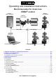
Operating and Installation Instructions Monitoring system for steam traps Central status indication CONA®-control Bolt-on Test chamber External Test chamber Bus circuit PC connection Tree topology Linear topology Contents 1.0 General information on Operating Instructions ........................................................................... 2-3 2.0 Notes on possible dangers............................................................................................................. 2-3 2.
Operating and Installation Instructions CONA®-control 5.0 Installation...................................................................................................................................... 2-13 5.1 General notes on installation ......................................................................................................................... 2-13 5.2 External test chamber ...................................................................................................................
Operating and Installation Instructions CONA®-control 1.0 General information on Operating Instructions These Operating Instructions provide information on mounting, operating and maintaining the valves and electronics. Please contact the supplier or the manufacturer in case of problems which cannot be solved by reference to the Operating Instructions. They are binding for transport, storage, installation, start-up, operation, maintenance and repair.
Operating and Installation Instructions CONA®-control 3.0 Storage and transport ATTENTION ! - Protect against external shocks (impact, vibration, etc.). - Valves must not be used to absorb external forces, e.g. they are not designed to be used as climbing aids or as attachment points for lifting gear. - Suitable handling and lifting equipment must always be used. Refer to the data sheet for weights. - Store the device in a dry, dirt-free location (temperature range: -40°C to +85°C.
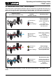
Operating and Installation Instructions CONA®-control 4.2 Operating principle The test chambers, which resemble a syphon, are installed either directly in front of or on the steam trap. If the steam trap is leaking steam, the condensate level on the input side is forced downwards by the steam pressure. If the steam trap is blocked, condensate collects upstream of it. The accumulated condensate and the condensate in the test chamber cool down.
Operating and Installation Instructions CONA®-control The central status indication integrates an AS-i power supply and an AS-i master / gateway. It allows up to 30 steam traps to be centrally monitored. The AS-i master / gateway has a PROFIBUS interface as standard to enable all status indications to be evaluated by a higher-level control. Faults that are indicated when the plant or part of the plant is started up or shut down can thus be reliably suppressed.
Operating and Installation Instructions CONA®-control 4.3 Indications on the CONA®-control system The LEDs on the "central status indication" light up continuously to indicate the existence of a fault. As soon as the steam trap functions correctly again, the LEDs blink to show that the faults are no longer present. By pressing the Reset button, you can reset a stored fault.
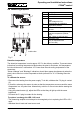
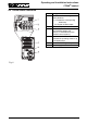
Operating and Installation Instructions CONA®-control 4.4 Measuring amplifier No. 1 2 3 4 5 6 7 8 Designation Status LEDs Contacts for sensor DC or AS-i circuit Input: Input voltage 30 V DC Potentiometer for calibrating temperature sensors LEDs for calibrating temperature sensors Potentiometer for setting blockage detection temperature (default: 95°C) LED - Relay or AS-i bus card Addressing plug (only in conjunction with AS-i bus card) Inside view Fig.
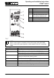
Operating and Installation Instructions CONA®-control 4.5 Central status indication No. 1 Designation Reset button for resetting stored fault indications < 2 s: Resets the corresponding steam trap 2 3 4 5 6 > 2 s: Resets all steam traps Power LED per indication card Fault indications for the corresponding steam trap (refer to "4.3 Indications on the CONA®-control system") Indication card Indicates the operating states of up to 30 steam traps AS-i / PROFIBUS gateway Power supply Fig. 6 Rev.
Operating and Installation Instructions CONA®-control 4.5.1 AS-i / PROFIBUS gateway No. 1 2 3 4 5 6 7 Designation Status LEDs PROFIBUS connector Digital display If a "fault" is indicated, the number of the faulty slave and the reason for the fault are shown by a dot Buttons for manual control AS-i power supply AS-i circuit Fig. 7 i NOTE ! - Never connect slaves or repeaters to the power supply cable (ASI PWR). - Never connect AS-i power supplies or other masters to the AS-i connecting cable.
Operating and Installation Instructions CONA®-control 4.6 Power supply No. 1 2 3 4 5 6 7 Designation AC input: Input voltage 85 - 264 V AC, frequency 45 - 65 Hz DC output: Output voltage 30 V DC Floating EFD output DC OK LED (green) EFD LED (red) Reset button EFD int./ext. switch Fig.
Operating and Installation Instructions CONA®-control 4.7 Technical data 4.7.1 Test chamber NOTE ! i For the technical data of the test chambers, e.g. - Principal dimensions, - Pressure-temperature ratings, limits of use, - Valves with different types of connection, etc. refer to the data sheet. 4.7.
Operating and Installation Instructions CONA®-control 5.0 Installation 5.1 General notes on installation ATTENTION ! - All work on electrical installations or equipment must be carried out by a qualified electrician, or by another suitably trained person under the guidance and supervision of a qualified electrician, in accordance with the locally applicable electrical rules and regulations. - The power supply cable must be disconnected from the mains (i.e.
Operating and Installation Instructions CONA®-control 5.2 External test chamber i NOTE ! Note the installation position of the external test chamber! - In the flow direction directly in front of the steam trap, - Horizontal, - Screw cap / cover pointing downwards! Steam trap External test chamber with sensor Flow direction Fig. 9 5.2.
Operating and Installation Instructions CONA®-control 5.3 Bolt-on test chamber ATTENTION ! - Make sure the inlet and outlet are shut off prior to all work on the steam trap. The device must be de-pressurised and cooled down! i NOTE ! Note the installation position! - Test chamber pointing diagonally downwards. - For correct function of the bolt-on test chamber, the outlet pipes must always be at the lowest point of the body. Otherwise steam flow can not be detected.
Operating and Installation Instructions CONA®-control - Even though communication via the AS-Interface cable is insensitive to electromagnetic interference, this cable should nevertheless be laid separately from any power cables. This also applies inside the cabinet! - Each AS-Interface line must have its own cable. AS-Interface cables must not be laid together with other cables in a bus. - If, in exceptional cases, single cores are used (e.g. inside the cabinet), always lay parallel core pairs.
Operating and Installation Instructions CONA®-control 5.5 Measuring amplifier 5.5.1 Notes on installation ATTENTION ! - The mains voltage must coincide with the values indicated on the rating plate. - Never touch live parts while carrying out adjustments! - Exercise particular caution when working with voltages higher than 24 V! - Never insert or withdraw modular isolating terminals that are still live! 5.5.
Operating and Installation Instructions CONA®-control 5.5.4 Circuit diagram Single operation without central status indication Sensor Measuring amplifier Sensor Measuring amplifier Power supply Sensor Sensor Single operation without central status indication with relay outputs Measuring amplifier Measuring amplifier Power supply K1 = Cold condensate K2 = Steam flow Fig. 13 Page 2-18 Rev.
Operating and Installation Instructions CONA®-control 5.5.5 Connection In the delivery condition the sensor is mounted in the test chamber and connected with cable lugs in the measuring amplifier. The plug-in contacts of the measuring amplifier are marked with the same colours as the sensor wires.
Operating and Installation Instructions CONA®-control 5.6 Central status indication 5.6.1 Notes on installation ATTENTION ! - The mains voltage must coincide with the values indicated on the rating plate. - Never touch live parts while carrying out adjustments! - Exercise particular caution when working with voltages higher than 24 V! - Never insert or withdraw modular isolating terminals that are still live! 5.6.2 Installation procedure Fig. 16 Page 2-20 Rev.
Operating and Installation Instructions CONA®-control 5.6.3 Circuit diagram Sensor Measuring amplifier Central status indication AS-i power supply AS-i master Sensor Measuring amplifier Indication card (max. 30) Standard PROFIBUS Fig. 17 5.6.4 Connection The power supply and the AS-i gateway are equipped with plug-in spring terminals. The device can thus be connected quickly and easily, and if the terminals need to be disconnected, the disconnected state is clearly visible.
Operating and Installation Instructions CONA®-control Connect a suitable fuse upstream in all DC applications! i NOTE ! If the internal fuse trips, the device is probably defective. In this case, it should be returned to the factory for examination! An all-pole disconnect switch must be provided for two-phase operation, i.e. if the device is connected to two external conductors of a three-phase system.
Operating and Installation Instructions CONA®-control 6.0 Putting the system into operation ATTENTION ! - The central status indication and the measuring amplifiers are only allowed to be operated without the hood / cover in case of essential adjustment work. Some non-insulated parts of the central status indication are live (dangerous voltage!) while this work is taking place.
Operating and Installation Instructions CONA®-control 6.2 Measuring amplifiers with a central status indication - Switch on the mains voltage Thirty measuring amplifiers and thirty indication cards are configured / preset in the factory. If these settings are not correct, the system indicates a "fault" and shows the incorrectly configured slaves (measuring amplifiers and indication cards) on the AS-i / PROFIBUS gateway. The type of slave fault is indicated by a dot.
Operating and Installation Instructions CONA®-control 6.2.1 Setting the PROFIBUS-DP address The AS-i / PROFIBUS gateway is set in the factory to PROFIBUS address 3. To change the PROFIBUS address, press the "Mode" and "Set" buttons on the AS-i / PROFIBUS gateway for at least five seconds. The current PROFIBUS address is then displayed, e.g. 003. By pressing the "Set" button, you can change the PROFIBUS address (up to a maximum of 126) in increments of 1.
Operating and Installation Instructions CONA®-control To delete a slave address: - Change to configuring mode: There must not be a bus connection to a higher-level system. Disconnect the bus connector (if connected). Press the "Mode" button for at least five seconds. The "prj mode" LED lights up and the connected slaves are shown in the digital display for 0.5 seconds. - When the slave address you want to change appears, press "SET". The display stops scrolling.
Operating and Installation Instructions CONA®-control Byte 27 26 25 24 23 Slave 12A Measuring Amplifier 6 Steam Leakage Blockage - Steam Leakage Blockage - - Steam Leakage Steam Leakage Blockage - - Steam Leakage Blockage - Steam Leakage Blockage - - Steam Leakage Blockage - Steam Leakage Blockage - - Steam Leakage Blockage - Steam Leakage Blockage - Blockage - Steam Leakage Blockage Steam Leakage Blockage - - - - - - - - Slave 23A Measuring Amplifier -
Operating and Installation Instructions CONA®-control Byte 27 26 25 24 23 Slave 12B Indication Card 22 - Reset button - - Reset button - - - Reset button - Reset button - Reset button - Reset button - Reset button - Reset button - Reset button Reset button - Page 2-28 - Reset button - - - - - - - - - - - Slave 29A Indication Card - - Slave 30A Indication Card 31 - Slave 27A Indication Card - - Reset button - Slave 28A Indication Card 30 - Slave 25A Indic
Operating and Installation Instructions CONA®-control Output data according to AS-i V2.
Operating and Installation Instructions CONA®-control Byte 27 26 25 24 23 22 Slave 30A 15 - - 21 20 Slave 31A LED-Trap Inspect - Not assigned Not assigned Not assigned Not assigned Slave 1B 16 Reserved - - Slave 2B 17 - - - - LEDSteam Leakage LEDBlockage - - - - LEDSteam Leakage LEDBlockage - - - - LEDSteam Leakage LEDBlockage - - - - LEDSteam Leakage LEDBlockage - - - - LEDSteam Leakage LEDBlockage - - - - LEDSteam Leakage LEDBlockage - - - - L
Operating and Installation Instructions CONA®-control Byte 27 26 25 24 23 22 Slave 24B 28 - - - - LEDSteam Leakage LEDBlockage - - - - - LEDBlockage Slave 27B LEDSteam Leakage LEDBlockage - LEDSteam Leakage - LEDBlockage Slave 29B LEDSteam Leakage LEDBlockage - LEDSteam Leakage - Slave 30B 31 LEDSteam Leakage - Slave 28B 30 20 Slave 25B Slave 26B 29 21 LEDBlockage Slave 31B LEDSteam Leakage LEDBlockage Not assigned Not assigned Not assigned Not assigned 6.
Operating and Installation Instructions CONA®-control 6.3.2 Shutting down the plant "Blockage" and "Steam Leakage" faults may be indicated at different times when the plant is shut down. Depending on the type of steam trap or the plant operating conditions, condensate may (re-)accumulate in the test chamber so that only "Blockage" is indicated.
Operating and Installation Instructions CONA®-control 8.0 Troubleshooting In the event of a malfunction or faulty operating performance, check that all installation and adjustment work has been carried out and completed in accordance with these Operating Instructions. If you cannot correct the fault with the help of the table in section "9.0 Troubleshooting table", please consult the supplier or manufacturer. 9.0 Troubleshooting table ATTENTION ! - Read sections 10.0 and 11.
Operating and Installation Instructions CONA®-control 9.
Operating and Installation Instructions CONA®-control 9.
Operating and Installation Instructions CONA®-control 11.0 Warranty / Guarantee The extent and period of warranty cover are specified in the "Standard Terms and Conditions of Albert Richter GmbH & Co. KG“ valid at the time of delivery or, by way of departure, in the contract of sale itself. We guarantee freedom of faults in compliance with state-of-the-art technology and the confirmed application.