User Manual ARGTEK GM5 WLAN 802.11b/g/n USB adapter WLAN USB Adapter for 802.
Contents Chapter 1 Getting Start ...................................................................... 3 Minimum System Requirements .................................................................................. 3 Optimize Wireless Performance ................................................................................... 3 Installation................................................................................................................. 5 Uninstall .......................................
Chapter 1 Getting Start Minimum System Requirements Pentium® 300 MHz or higher compatible processor At least one available USB 2.0 or 1.1 port The installation CD 5Mbytes free hard disk space. Windows 2000, XP, XP professional, Vista, or Windows 7. If you do not have a USB 2.0 port on your computer, the throughput of the USB adapter will be limited to the 14 Mbps of the USB 1.1 standard. Windows XP users must install SP2 or above for the Hot fix which fixes the USB 2.
Avoid obstacles to wireless signals. Keep your wireless devices far away from metallic file cabinets, refrigerators, pipes, metal ceilings, reinforced concrete, and metal partitions. Keep away from large amounts of water such as fish tanks and water coolers. Reduce interference Keep away from computers, cordless phones, cell phone, coping machine and fax machines. Keep away from microwave oven. Site survey nearby wireless devices to determine your operating channel.
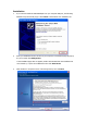
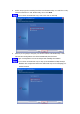
Installation 1. If you insert the Wireless LAN USB Adaptor into your computer USB port, the following hardware setup wizard will pop up. Click Cancel to install driver from installation CD. 2. Insert your installation CD into CD drive of your computer. An installation page will pop up for you to install. Click Utility Driver. If the installation page does not appear, double click CD-ROM drive the installation CD was inserted to, or open the CD-ROM drive then click Autorun.exe 3.
4. Select setup type for installing both driver and WLAN utility or install driver only. Choose Install driver and WLAN utility, then click Next If you choose to install driver only, refer to the note on next step. 5. Select if you are going to configure your wireless network with WLAN utility or with Microsoft Zero Configuration tool. Choose WLAN Utility then click next. Type of configuration tool can be changed after installing this software.
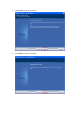
6. Click Install to begin the installation. 7. Click Finish to complete installation.
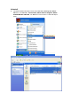
Uninstall A. Uninstall the WLAN USB Adaptor Driver from start menu, All Programs, Ralink Wireless, click Uninstall or Control Panel, Add or Remove Programs, Ralink RT2870 Wireless LAN Card, click Remove to remove Wireless LAN USB Adaptor driver.
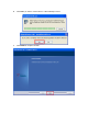
B. Click Yes if you want to remove Wireless LAN USB Adaptor driver. C. Click Finish to complete uninstall.
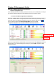
Chapter 2 Management Guide Making a Basic Network Connection Select a configuration tool In the following instruction for making a network connection, we use WLAN utility to configure your wireless network settings that was installed as the steps in previous chapter. To connect with 802.11 bgn Wireless LAN Utility As default, the WLAN Utility is started automatically upon starting your computer and connects to the first available network.
To connect with Microsoft Zero Configuration To switch between the configuration tools, please right click on the icon on system tray. Select Use Zero Configuration as Configuration Utility , double click on icon on system tray. The Zero Configuration pop up and show available wireless networks.
A pop up dialog allow you to setup your security key, then click Connect to join a network by Zero configuration.
Chapter 3 Introduction to the Wireless LAN Utility Utility Interfaces This Utility is basically consisted of three parts: 1. Button Section: on top of the window. Include buttons for selecting the Profile page, Network page, Advanced page, Statistics page, WMM page, WPS page, the About button, Radio On/Off button and Help. 2. Function Section: center of the Utility window. Appears to present information and options related to the button. 3. Status Section: bottom of the utility window.
When starting utility, a small utility icon appears in the system tray of the taskbar. You can double click it to maximize the dialog box if you selected to close it earlier. You may also use the mouse's right button to close utility. Additionally, the small icon will change color to reflect current wireless network connection status. The status is shown as follows: : Indicates the connected and signal strength is good. : Indicates the connected and signal strength is normal.
Network Items Status Extra Info Channel Authentication Encryption Network Type IP Address Sub Mask Default Gateway Link Speed Throughput Link Quality Signal Strength 1 Signal Strength 2 Signal Strength 3 Noise Strength HT Information Shows the connecting status. Also shows the SSID while connecting to a valid network. Display link status in use. Display current channel in use. Authentication mode in use. Encryption type in use. Network type in use. IP address of current connection.
Profile This profile page allows users to save different wireless settings, which helps users to get access to wireless networks at home, office or other wireless network environments quickly. Items Profile Name SSID Network Type Information Choose a name for this profile, or use default name defined by system. Fill in the intended SSID name or use the drop list to select from available Aps. There are two types, infrastructure and 802.11 Ad-hoc modes.
2. Auth./Encry.: to fill in wireless encryption or authentication information. Click Use 802.1X checkbox will enable 802.1x tab 3. 802.1x: to configure the authentication information for 802.
Advanced This page provides advanced configurations to this adapter. Please refer to the following chart for definitions of each item. Items Wireless mode Enable TX Burst Enable TCP Window Size Fast Roaming at __ dBm Show Authentication Status Dialog TX Rate Select Your Country Region Code Information Click the drop list to select a wireless mode. Select to enable connecting to a TX Burst supported device. Mark the checkbox to enable TCP window size, which help enhance throughput.
Statistics Statistics page displays the detail counter information based on 802.11 MIB counters. This page translates the MIB counters into a format easier for user to understand. Items Information Frames Transmitted Successfully Frames successfully sent. Frames Retransmitted Successfully Successfully retransmitted frames numbers. Frames Fail To Receive ACK After All Retries Frames failed transmit after hitting retry limit. Reset Counter Reset counters to zero.
WMM This page allows users to activate the WMM function for this device. Please note that this function only works while connecting to a WMM compatible device. Items WMM Enable WMM - Power Save Enable Direct Link Setup Enable MAC Address Timeout Value Apply / Tear Down Information Enable Wi-Fi Multi-Media. Enable WMM Power Save. Please enable WMM before configuring this function. Enable DLS (Direct Link Setup). Please enable WMM before configuring this function.
WPS WPS Configuration: The primary goal of WiFi Protected Setup (WiFi Simple Configuration) is to simplify the security setup and management of WiFi networks. This adapter supports the configuration setup using PIN configuration method or PBC configuration method through an internal or external Registrar. Items WPS AP List Information Display the information of surrounding APs with WPS IE from last scan result. List information includes SSID, BSSID, Channel, ID (Device Password ID), and Security-Enabled.
When you click PIN or PBC, please don't do any rescan within two-minute connection. If you want to abort this setup within the interval, restart PIN/PBC or click Disconnect to stop WPS action.
CCX Items Information Enable CCX (Cisco Choose whether Cisco Compatible eXtensions are supported or not. Compatible eXtensions) Enable Radio Measurement Enable the radio measurement; the non-serving channel measurement limit is between 0 and 1023 milliseconds.
Radio On/Off Click on the button to enable/disable wireless connection status.
About Display Configuration Utility, Driver, and EEPROM version information. Display Wireless NIC MAC address.
Chapter 4 AP mode management guide Clicking will bring up the selection window and let the user make a selection. It can switch to AP mode as shown figure. If "Switch to AP mode" is selected, the system will display default information when switching to AP mode. The dialog box is shown in figure Note: The country code selection is for non-US model only and is not available to all US model. Per FCC regulation, all WiFi product marketed in US must fixed to US operation channels only.
There are six tabs to configure the settings. Config Settings: This tab is used to configure Soft AP. Access Control: This tab is used to edit the access control list. Mac Table: This tab displays the stations which are currently connected to Soft Event Log: This tab displays the Soft AP events. Statistics: This tab displays the packet counters. About: This tab displays the Ralink driver and utility information. AP.
Config Setting User can set and display detailed Soft AP information in this dialog box. Items SSID Wireless Mode Country Region Code Beacon (ms) TX Power Idle Time Wireless Protection Channel TX Rate Information AP name of user type. The user also can select [Use Mac Address] to display it. System default is SoftAP-XX (XX is last two numbers of MAC address). Select wireless mode. 2.4G and 5G are supported. System default is 2.4G. ( 802.
Use Mac Address Security Setting No forwarding among wireless clients Hide SSID Allow BW40 MHz Default Cancel Apply: Use the MAC address of wireless card as the AP’s name. System default is APX. (X is last number of Mac Address.) Authentication mode and encryption algorithm used by the AP. The system default is no authentication and encryption. If there is no beacon among the wireless clients, they can’t share information with each other. The system default is no forwarding. Don’t display the AP name.
Access Control AP connected or can’t connect with Mac address that user setting. Items Access Policy Mac Address Access List Delete Remove All Apply Information There are three policies available in the drop-down list. They are Disable, Allow All, and Reject All. System default is disabled. In order to add an entry into the access control list, the user should input the MAC address without "-" in the text box and then click the "Add" button. Display all Mac Addresses that the user has set.
MAC Table Shows link status. It displays detailed station information of current connection. Items MAC Address AID Power Saving Mode Status Information The station’s Mac address of the current connection. The association identifier of the client. Support Power Saving Mode on the currently connected station. The link status of the current connection. (Only 802.
Event Log A record of all events, times and messages. Items Information Event Time (yy/mm/dd-hh:mm:ss) Specifies when the event occurred. Message All event messages.
Statistics The statistics page displays detailed counter information based on the 802.11 MIB counters. The information is translated into a format easier for the user to understand. Transmit Statistics Items Frames Transmitted Successfully Frames Fail To Receive ACK After All Retries Frames Retransmitted Successfully Information The number of frames sent successfully. The number of frames failed to transmit after hitting the retry limit The number of successfully retransmitted frames.
About The About page displays the wireless card and driver version information, displays Configuration Utility, driver and EEPROM version information, displays Wireless NIC MAC address.