Proprietary Statement This manual contains proprietary information of Argox Information Co., Ltd. It is intended solely for the information and use of parties operating and maintaining the equipment described herein. Such proprietary information may not be used, reproduced, or disclosed to any other parties for any other purpose without the expressed written permission of Argox Information Co., Ltd. Product Improvements Continuous improvement of products is a policy of Argox Information Co., Ltd.
A Letter to Our Customers Dear Customers, Congratulation on selecting an Argox Refine series printer! We believe soon you will find that you have made a cleverest choice! This booklet is a small gift from us. It is intended for helping you to know your printer better, then further to optimize it. Basically, this booklet contains two parts: operation guidance and related valuable information.
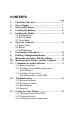
CONTENTS Page 1. 2. 3. 4. 5. Checking Your Box…………………………….. 5 Power Supply…………………………………… 7 Parts and Features……………………………... 8 Loading the Ribbon……………………………. 10 Loading the Media……………………………... 15 5.1 Standard Mode 5.2 Peel Off Mode 5.3 Cutter Mode 6. Operator Controls……………………………… 25 6.1 Power Switch 6.2 Buttons 6.3 LED Indicators 7. 8. 9. 10. 11. Performing Calibration………………………... Printing Configuration Report………………... Returning to Factory Default Settings...
14. Reference Technical Information……………... 52 14.1 General Specifications 14.2 Fonts, Bar Codes and Graphics Specification 14.2.1 Printer Programming Language A, PPLA 14.2.2 Printer Programming Language B, PPLB 14.2.3 Printer Programming Language Z, PPLZ 14.3 Interface Specifications 14.3.1 Introduction 14.3.2 Serial 14.3.3 USB 14.3.4 Connection with host 14.3.5 Parallel ( Centronics ) 14.3.6 Auto Polling 14.4 ASCII TABLE 15. Appendix……………………………... ………... 62 15.1 Appendix A : Printer Status 15.
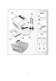
1. Checking Your Box Receiving the box of your printer, you are advised to check first for the possible shipping damage. There are two ways you can do it: 1.1 Inspect the outer appearances of both the box and the printer for possible damage. 1.2 Raise the top cover of the printer to see if the media compartments are in order. If damages did occur, immediately file the claim to the shipping company for settlement.
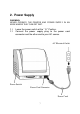
2. Power Supply WARNING: NEVER OPERATE THE PRINTER AND POWER SUPPLY IN AN AREA WHERE THEY CAN GET WET. 2.1 2.2 Leave the power switch at the “ O ” Position. Connect the power supply plug to the power cord connecter and the other end to your AC source.
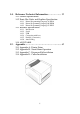
3.
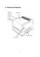
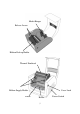
Media Hanger Release Levers Ribbon Pick-up Holder Thermal Printhead Ribbon Supply Holder Platen Cover Lock Roller 9 Power Switch
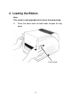
4. Loading the Ribbon Note: This section is not applicable to the direct thermal printing. 4.
4.2 4.3 Unlatch the print head module by pushing the two green release levers on the sides toward the rear. This allows print head module to rotate upward automatically and expose the ribbon supply holder.
4.4 4.5 4.6 Unwrap the ribbon roll pack and separate the ribbon roll and the bare core. Attach the edge of the ribbon on the bare core and wind it a little bit onto the core. Insert the ribbon roll into the supply holder. (First snap in the right side and then the left side.) Ribbon Roll Bare Core Noted: It is the figure illustrating ribbon wound ink-side in for R-400plus/R-600. For R-400K plus model, please use ribbon wound coated side out.
4.7 Turn back the print head module and then insert the bare core into the pick-up holder. (First snap in the right side, then the left side.
4.8 4.9 Turn the wheel of the print head module to ensure the ribbon is tightly wound. Press down the print head module firmly on both sides till you hear a snap. Wheel Print Head Module Note: 1. R-400plus / R-600 use ribbon wound coated side in. R-400K plus use ribbon wound coated side out. 2. Optional ribbon core adapter is available once ribbon width is less than 4’’ width.
5. Loading the Media R-Series printers can be operated in three different options: standard, peel-off, or with a cutter. - - Standard mode allows you to collect each label freely. In peel-off mode, the backing material is being peeled away from the label as it is printed. After the former label is removed, the next one will be printed. In cutter mode, the printer automatically cuts the label after it is printed.
5.1 Standard Mode 5.1.1 Press the cover locks on both sides to swing the top cover toward the rear and expose the media compartment. 5.1.2 Load the media roll onto the media hanger. 5.1.3 Put the media roll on the hanger holder.
5.1.4 Unlatch the print head module. 5.1.5 Hold the print head module upright with one hand to allow the media pass under it. Lead the media through the media guides with the other hand. The media guides can be adjusted centrality to well fit with different label width. 5.1.6 Route the media through the media sensor for media detection. 5.1.7 Lead the media over the platen roller.
5.1.8 Turn back the print head module and then press it down firmly on both sides till you hear a snap.
5.1.9 Close the top cover and turn on the printer or press feed button if the printer is already on. Feed Button Note: 3” holder paper is available for 3” ID media roll.
5.2 Peel Off Mode (Installing the dispenser kit, please refer to the Appendix C.) Follow the common procedure of "Loading the Media "of Standard Mode from step 5.1.1 to step 5.1.9. 5.2.1 Remove approximate 6" long labels from the backing paper.
5.2.2 Trim the edge of label backing paper with scissors or knife. 5.2.3 Push down peeler-switch to ease the access packing paper. 5.2.4 Lead the backing paper over the plate, then thread it back into the slot, ensuring that it is inserted between white plastic roller and plate. 5.2.5 Pull back the peeler-switch to secure backing paper.
5.2.6 Latch print head module. 5.2.7 Turn on the printer and press feed button. 5.2.8 Labels will be separated from backing paper and fed out on H cover, while backing paper will come out from the slot under the H cover, and label will be fed out. 5.2.9 Close the top cover. Feed Button Label Backing Paper Note: The "FEED" button will not drive the printer to peel. The peeling work can be executed only when the software setting is ready.
5.3 Cutter Mode (Installing the cutter, please refer to Appendix D ) Follow the same procedure as "Loading the Media" from step 5.1.1 to step 5.1.9. 5.3.1 Mount cutter on print head module by fastening with two screws. 5.3.2 Thread the media over the platen roller, and then route the media through the slot of the cutter module. Screw Cutter Screw Note: Cutter baby board must be installed prior to cutter installation.
5.3.3 Press down the print head module firmly. Cutter Note: The "Feed" button will not drive the printer to cut. The cutting work can be executed only when the software setting is ready.
6. Operator Controls 6.1 Power Switch Controls printer power On-normal operation Off-the power should be turned off before connect or disconnect the communication cables and power cables 6.2 Buttons There are three buttons, each has two basic functions. BUTTON FEED PAUSE CANCEL Pressed at normal status Pressed during power-on Feed a label. Perform a self-test for configuration report. ■ Stop the printing process. Perform the media ■ Resume the printing job calibration. after press it again.
6.3 LED Indicators There are three LED indicators on the front panel, “READY”, “MEDIA” and “RIBBON”. These indicators display the operation status of the printer. READY The READY indicator will remain lighted except if any of the following conditions prevail. - Receiving data from host. - A fault condition. MEDIA The MEDIA indicator will remain on for the normal operation of the printer. - The printer is at PAUSE state. - Blinking – Media run out. (READY will be also blinking.
height). 3. Before calibration, the media and ribbon must be loaded properly and move the label sensor to correct position. 4. After self-test, the printer is at dump mode, If you need normal operation, you must press CANCEL to restart the printer.
7. Performing Calibration After the media loaded, it is necessary to do the calibration for the label size detection. 7.1 Press and hold the pause button. 7.2 Turn on the power. 7.3 Media indicators will blink, at this point release PAUSE button. 7.4 The printer will feed the labels for 6 inches. 7.5 Media indicators stop blinking and remain illuminated. Note: This procedure is very important and must always be carried out after installation and every time the media type is changed.
8. Printing Configuration Report 8.1 Performing the Self Test 8.1.1 8.1.2 8.1.3 8.1.4 8.1.5 8.1.6 report. Turn off the printer. Press and hold the feed button. Turn on the power. Ready indicator blinks, release feed button. The printer will print out a configuration report. Ready indicator stops blinking and lights up.
Note: 1. After self-test the printer will enter character dump mode. For normal operation press the cancel button to exit from dump mode. 2. On the report: PPLA – Present emulation type R2A0-1.00 – Firmware version 052302 – Date code Please provide the above information to Argox support team in case your printer has a printing problem.
9. Resetting the Printer to Factory Default Settings If you would like to reset the printer to its factory defaults after certain commands have been sent or settings changed: 9.1 Turn off the printer. Press and hold the CANCEL button. 9.2 Turn on the power. 9.3 Ribbon indicator blinks, release the button. 9.4 Ribbon indicator stops blinking and lights up. 9.5 The following parameters automatically reset.
10. Hooking up the Printer & Computer 10.1 Connecting the Printer to Your Host 10.1 You can connect the printer with any standard Centronics cable to the parallel port of the host computer. 10.2 Alternatively you can connect the printer with a serial cable to the RS232C port of your computer or terminal. (for PC compatibles, the RS232C port is COM1, COM2 or COM3.) Note : Using Centronics allows for a much higher communication speed than the use of a serial.
11. Communicate with the Printer The bundled printer driver can be applied to all applications under Windows XP/ Vista/ Windows 7, supporting 32-bit/ 64-bit operation systems. With this driver you can operate any popular Windows software applications including Argox Bartender UL label editing software or MS Word, etc., to print to this printer. 11.1 Before installation The following installation steps are based on R-400plus as an example.
1. Turn off the printer. Plug the power cable into the power socket on the wall, and then connect the other end of the cable to printer's power socket. Connect the USB cable to the USB port on the printer and on the PC. 2. Turn on the printer. If the printer supports Plug-and-Play, and you have successfully connected it using a USB cable, then the Windows Add Hardware Wizard will automatically detect the printer and display a dialog that allows you to install a driver.
4.
Instead of the flash prompt above, another way to install Seagull driver is to run the DriverWizard utility from the Installation Directory where the Seagull driver files locates. 5. On the Seagull Driver Wizard prompt, select the first radio button to “Install a driver for a Plug and Play printer”: Argox R-400plus PPLB USB002 Then click “Next.
6. Enter Printer name (i.e. Argox R-400plus PPLB) and select "do not share this printer”, and click "Next" Argox R-400plus PPLB 7. Check all the data on the showing screen, if it is correct, click "Finish".
8. After the related files have been copied to your system, click "Finish". Installing printer „Argox R-400plus PPLB‟… 9. After driver installation is complete, click "Close". The driver should now be installed.
11.3 Installing a Printer Driver (for other interfaces except USB) 1. Turn off the printer. Plug the power cable into the power socket on the wall, and then connect the other end of the cable to printer's power socket. Connect the Parallel cable, Serial cable, or Ethernet cable to the proper port on the printer and on your computer. 2. Prepare the documentation and software CD-Rom from printer package and then install to CD-Rom drive of your computer. The CD-Rom will bring out the following prompt.
3.
Instead of the flash prompt above, another way to install Seagull driver is to run the DriverWizard utility from the Installation Directory where the Seagull driver files locates. 4. On the prompt, Windows Printer Driver, select “I accept…” and click "Next". 5. Assign the directory to keep Seagull driver, (for example: C:\Seagull) and click "Next".
6. Click "Finish". 7. Select Install printer drivers and Click "Next" 8.
Argox R-400plus PPLB 9. Select the port of the printer and click "Next". LPT1 Parallel Port40 PPLB 10. Enter Printer name (i.e. Argox R-400plus PPLB) and select "do not share this printer”, and click "Next".
Argox R-400plus0 PPLB 11. Check all the data on the showing screen, if it is correct, click "Finish". Argox R-400plus PPLB LPT1 Argox R-400plus PPLB 12.
"Finish". Installing printer „Argox R-400plus PPLB‟… 13. After driver installation is complete, click "Close". The driver should now be installed.
12. Troubleshooting Generally, when a malfunction or an abnormal condition occurs, the “READY” LED will keep blinking and printing and communication between the host and printer will stop. To understand what the problem, please check the LEDs. 12.1 Problems on media Possible Problems Missing gap Solutions Remarks . Check the media path. . Check the position of label sensor. If you use continuous media, check your application software and driver. You should select continuous. Media out .
12.2 Problems on ribbon Possible Problems Ribbon has run out Solutions Remarks Supply the ribbon roll. Ribbon jam Ribbon sensor error Recover the jam. Replace the ribbon sensor. Does not apply to direct thermal. If you use direct thermal, set bit 1 of DIP switch to OFF. not for direct thermal. not for direct thermal. 12.3 Miscellaneous 12.3.1 The host shows “Printer Time out”. 1.
12.3.3 Vertical streaks in the printout usually indicate a dirty or faulty print head. Clean the print head first, if they still persist, replace the print head. 12.3.4 Unstable ribbon roll rotation. Check the label path and make sure the head latch is securely closed. 12.3.5 Poor printout quality. . The ribbon may be not qualified. . The media may be not qualified. . Adjust the Darkness (heat temperature). . Slow down the print speed. . Refer to the following paragraphs and clear the related modules. 12.
13. Caring for your Printer Before maintenance be sure to turn off the printer power. 13.1 Cleaning the print head (TPH) To keep the Print Head remain in the best conditions and efficiency and to extend duration for use, regular cleaning action is needed. Clean the print head as follows: 1. Turn off the printer. 2. Open the top cover to access the print head module 3. Remove the ribbon. 4. Rub the print head with a cotton bud moistened with “Ethanol” or “IPA”. 5.
Cleaning Material Surface of print head‟s heating element is very fragile. To prevent from any possible damage, please use soft cloth/ cotton buds with “Ethanol” or “IPA” to clean print head surface. It‟s strongly recommended to wear hand gloves during cleaning progress. Do not touch print head surface by bare hands or with any hard equipment. Water or spit should be kept away in case of corrosion on heating elements.
13.2 Cleaning the roller Using a cotton moistened with alcohol, clean the roll and rip off the attached glue. Note : The roller should be cleaned whenever it has been in contact with foreign materials such as dust or adhesives. 13.3 Cleaning the media compartment Clean the media compartment with cotton, which has been moistened with a mild detergent. Every time a media roll is printed this compartment should be cleaned to reduce the incidence dust.
14. Reference Technical Information 14.1 General Specifications Specifications R-400plus R-600 Printing method Direct thermal & Thermal Transfer Printing resolution 203 dpi 300 dpi Printing speed 2~6 2~4 (ips) Printing length 0.4 ~ 43 0.4 ~ 30 (in.) Printing width Max 4.25 Max 4.
Ribbon Mechanism request Dimension Weight Power source Operation environment Optional items Agency listing Wax, Wax/Resin, Resin Ribbon width – 1”~4” Ribbon roll – max 2.67” (OD 68 mm) Ribbon length – max 360m wax, 300m resin Core size - ID 1” core (25.4 mm) Ribbon wound ink-side in: R-400plus/ R-600; Ribbon wound ink-side out: R-400K plus Built-in Tear off bar, front-open cover, clear window, fan fold paper back cover, face-in ribbon run way, un-adjustable TPH carrier. W 314 x H 231 x L 218 mm 9.
14.2 Fonts, Bar Codes and Graphics Specification The specifications of fonts, bar codes and graphics depend on the printer emulation. The emulation is a printer programming language, through which the host can communicate with your printer. There are printer PPLA / PPLB programming languages for R-series. 14.2.
Stand-alone operation ArgoKee 14.2.2 Printer Programming Language B, PPLB Specification General fonts Symbol sets (Code pages) Soft fonts Font expandability Bar code types Graphics Stand-alone operation R-400plus / R-600 5 fonts with different point sizes 8 bits: code page 437, 850, 852, 860, 863 and 865. 7 bits: USA, British, German, French, Danish, Italian, Spanish, Swedish and Swiss.
14.2.
14.3 Interface Specifications 14.3.1 Introduction This appendix presents the interface specifications of I/O ports for the printer. These specifications include pin assignments, protocols and detailed information about how to properly interface your printer with your host or terminal. 14.3.2 Serial The RS232 connector on the printer side is a female, DB-9.
14.3.3 USB 2 1 3 4 USB series “B” Receptacle Interface Pin 1 2 3 4 Signal Name VBUS DD+ GND Connector Terminal Pin Assignment 14.3.
Alternatively you can just connect the 3 wires in the following way.
Handshaking : XON/XOFF as well as CTS/RTS (hardware flow control). If you run an application with the bundled printer driver under Windows and use the serial port, you should check the above parameters and set the flow control to “Xon/Xoff” or “hardware”. 14.3.5 Parallel (Centronics) The parallel port is a standard 36-pin Centronics. Its pin assignments are listed as following.
14.3.6 Auto Polling Both the serial and parallel ports are active at the same time on this printer, i.e. data can be received on either one, however no provision is made for port contention. If data is transmitted to both ports simultaneously, it will cause the data in the received buffer to be corrupted. 14.4 ASCII TABLE 0 1 0 NUL 1 SOH XON 2 STX 3 XOFF 4 5 NAK 6 ACK 7 BEL 8 BS 9 A LF B ESC C FF D CR E SO RS F SI US 2 ! “ # $ % & „ ( ) * + , .
15. Appendix 15.1 Appendix A: Printer Status Blinking LED MEDIA MEDIA READY RIBBON READY READY Description The printer is at pause state. Press PAUSE or CANCEL to return to normal state. The media is uninstalled or used up. Load new media to the printer. The ribbon is uninstalled or end-of-ribbon occurred. Load new ribbon to the printer. If you just use thermal media set bit 1 of DIP switch to OFF position. The format or baud rate of the RS232 communication is inconsistent between the printer and host.
15.2 Appendix B: Stand-Alone Operation Stand-Alone operation for keyboard and barcode reader Apart from related hardware devices and PPLB emulation, in order to use keyboards and barcode readers (scanner) you should follow apply with ArgoKee. 15.3 Appendix C: Dispenser Kit installation 1. 2. Turn off the power switch. Remove the top cover and middle cover.
3. 4. Remove gear (27) and (31). Plug spring–peeler (83) into the right hole on chassis 2 and lock screw (F) up. 5. Put shaft-peeler (86) and peeler-switch (88) into shaft-peeler (87) and then insert it in hole on right side. 6. Guide peeler-switch (85) go through shaft-peeler (87). 7. Hook spring-peeler (83) on the circle notch of shaft-peeler (87). 8. Put spring-peeler (84) into the left hole of chassis 2 and lock screw (F) up. 9. Put peeler-switch (89) into shaft-peeler (87). 10.
11. Put back gear (27) and gear (31). 12. Mount the cable into chassis 2 and plug the other side into the label on the main board. 13. Close the middle cover.
15.4 Appendix D : Cutter Installation 1. Turn off the power switch. 2. Remove the top cover and middle cover.
1. Remove the E- ring(I), gear(27) and release the screw(F). 2. Remove the bracket-peeler(71) from the module. 3. Secure two attached screws (B) for the cable connector. 4. Add a baby board to JP29 on the main board. 5. Plug the cable connector into JP13, and make sure Jumper (J1) position is “2-3” 6. Click back the middle cover. 7. Click back the top cover. 8. Secure two attached screws (M) for the cutter. 9. Plug cutter cable into “ External Connector”.
Environmentally sensible disposal of electrical and electronic equipment Electrical and electronic equipment contains valuable materials that should be supplied to recycling or recovery. Please dispose of electrical and electronic equipment at qualified collecting points separate from municipal waste.