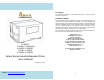
For Support For any issues or questions, contact SATO America, Inc. using the contact information shown here. Limitation of liability SATO Corporation and/or its subsidiaries in Japan, the United States, and other countries make no representations or warranties of any kind regarding this material, including, but not limited to, implied warranties of merchantability and fitness for a particular purpose.
Table of Contents 1. Getting Started 6 Unpacking Connecting the Power Cord Internal Parts and Features Loading Ribbon Switching Ribbon Wound Ink-side in or Ink-side out Loading Media Standard Mode Loading Me7dia Peel Off Mode Loading Media Cutter Mode Loading Media Adjust Position of Label Sensor 2.
Example: Making a Keyboard Form Stand-alone with Barcode Reader Example: Making a Barcode Reader Form 6. Technical Reference General Specifications Printer Programming Language A, PPLA Printer Programming Language B, PPLB Printer Programming Language Z, PPLZ Interface Specifications USB PS/2 Serial Interface Connection with Host: Parallel (Centronics) Ethernet Interface Auto Polling ASCII TABLE 103 107 108 1.
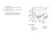
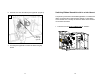
possible damage. 2. Open the top cover of the printer to see if the media compartments are in order. Note: If damage has occurred, contact your shipping company immediately to file a claim. Printer Quick Guide 3. Check whether you have received the following accessories together with the printer. If there are any items missing, please contact your local dealer.
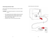
Connecting the Power Cord Connect the power cord as below. Before setting up and connecting the printer you should consider the following. WARNING! Do not operate the printer in an area where it might get wet. Find a solid flat surface with adequate room for the printer and enough space above for media and ribbon access. Place the printer within cable distance of the host and printer (serial or parallel cable.) Isolate the power cord from other electrical cables.
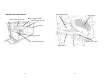
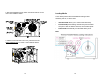
Internal Parts and Features Thermal Print Head Head Latch Ribbon Supply Spindle Media Supply Spindle Ribbon Pick-up Spindle Feed Slot Bracket Paper Sensor Guide Thermal Print Head Paper Roller Standard Mode 11 12
Loading Ribbon Note: Thermal Transfer printing requires media to print with appropriate ribbon. This section can be referred to, for X-Series to use transfer thermal printing. The sample steps below are based on ribbon wound ink-side in as an example.(X series printers use ribbon wound ink-side in as default. To change setting to ribbon would ink-side out, refer to Section - Switching Ribbon Wound Ink-side out or Ink-side in) Peel Off Mode 1.
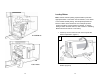
4. Lead the ribbon through the print head module. (Figure 4) 2 5. Attach the edge of the ribbon onto the bare core and wind it a bit onto the core. Make sure the coating side of the ribbon is face down. 4 Head Latch Bracket 3. Unwrap the ribbon and separate the ribbon roll from the bare core. Insert the ribbon roll onto the ribbon supply spindle.
6. Insert the core onto the ribbon pick-up spindle. (Figure 5) Switching Ribbon Wound Ink-side in or Ink-side out The printer is produced to suit flexible applications, no matter with ribbon wound ink-side in (manufacturing default), or with ribbon wound ink-side out. The steps to switch for ribbon wound ink-side out are listed as follows: 5 1. Pull and move the SHAFT RIBBON ADJ to “Outside”: Ribbon Ribbon Pick-up Pick-up Spindle Spindle 7.
2. After the adjustment above, ribbon wound ink-side out can be used. Then install the ribbon: Loading Media The X-Series printers offer three different loading modes: standard, peel-off, or with a cutter. Standard mode allows you to collect each label freely. Peel-off mode peels backing material away from the label as it prints. After the label is removed, the next label prints. Cutter mode automatically cuts the label after it prints. Note: 3.
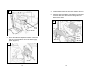
Standard Mode Loading Media 1. Insert the media roll into the media supply spindle and move the media guide to the inside. (Figure 1) 2. Turn the head latch counter-clockwise and open the bracket. Remove the outside media guide. (Figure 2) 2 1 Media Guide Head Latch Outside Media Guide Media Supply Spindle Bracket 3. Lead the media through the print head module and under the paper sensor guide.
3 5. Close the top cover and the front access door and turn on the printer, or press the “FEED” button if the printer is already on. (Figure 5) Print Head Module 5 Paper Sensor Guide Paper Sensor Position Lever 4. Return the outside media guide, close the bracket, and hook the head latch.
2. Lead the media backing paper through the print head module. (Figure 2) Peel Off Mode Loading Media Follow steps 1 to 3 in “Standard Mode Loading Media” above. 2 1. From the leading end of the media roll remove enough labels to expose 6-inches of backing paper. (Figure 1) 1 Print Head Module Backing Paper 3. Push down the peel-off mechanism release lever and lead the media under the peeler module.
4. Close the peeler module using the peel-off mechanism release lever. (Figure 4) 4 Notes: 1. The FEED button does not make the printer peel. To enable Peeling function, set by the LCD panel. 2. Make sure the peeler sensor is out of the ribbon path when installed. Peel Lever Dispenser Module 5. Close the top access door and turn on the printer or press the FEED button if the printer is already on.
2. Return the outside media guide, close the bracket, and hook the head latch. (Figure 2) Cutter Mode Loading Media Follow steps 1 to 3 in “Standard Mode Loading Media” above. 1. Insert the media into the print head module and under the paper sensor guide.
3. Close the top access door and turn on the printer or press the FEED button if the printer is already on. The printer will then feed the labels through the cutter automatically. (Figure 3) Cutter Note: Adjust Position of Label Sensor Function of the label sensor is to detect the gap, notch, or holes of labels, to help the printer for accurate print positions and label length. For labels with gaps, label sensor can be positioned wherever media locates.
2. Printer Operation The illustrations below describe parts and features of X-Series. Front Panel X-1000VL The front panel includes: 3 LED indicators (READY, MEDIA and RIBBON) 3 buttons (FEED, PAUSE and CANCEL) LCD display (except X-1000VL) Top Access Door Front Access Door LED Indicators LEDs and Buttons There are three LED indicators on the front panel - READY, MEDIA and RIBBON. These indicators display operation status of the printer.
direct thermal can be set via the printer panel. For the X-1000VL model, set via Printer Utility, Windows driver or printer commands. Buttons There are three buttons, each with two basic functions.
Setting Display Language If a keyboard is plugged in, the LCD display will indicate: X-2000V / X-2000V Zip / X-2300E / X-2300ZE READY (203,PPLB) The printer’s LCD display supports six languages: English, French, German, Italian, Spanish, and Portuguese.
Changing Settings from the Panel LCD Function Setting Procedure You may change settings using the buttons on the front panel of the X-2000V, X-2000V Zip, X-2300E, X-2300ZE, X-3200, X-3200Z, X-3200E, and X-3200ZE printer models, in addition to changing settings via software commands. PAUSE+CANCEL LCD indicating READY (203,PPLB) Change settings via buttons on panel: Buttons The following procedure is an example of setting procedure to direct thermal printing mode: Function Press to enter setting mode.
Item Range PRINT MODE DIRECT THERMAL/ Factory Default ALTERNATIVE 3 Remarks THERM. TRANSFER THERM. CUT PEEL OFFSET -15 ~ 50 mm 0 mm To adjust cut and peel positions. PRINT OFFSET -8 ~ 15 mm 0 mm Controls vertical print positions. Positive value only. TRANSFER AUTO-CAL. MODE MODE 1 MODE 1 MODE 2 MODE 3 MODE 4 Mode 1: Printer performs Auto Calibration after printing the first label, if label height differs from parameters in printer's flash.
CUTTER INSTALLED is set to “YES”. CUTTER W/O BACK PEELER INSTALLED NO READER INSTALLED NO WIN. CON. LEN. 0 ~ 254 mm NO BACK DISTANCE 10~40 mm 21 mm Available only when BACK FEED is enabled. BASE DARKNESS 0~99 (PPLA) 0 Available only in PPLA and PPLB printer languages. ABS. DARKNESS 0~30 0 To select darkness. Available only in PPLZ printer language. TRIM. -30~30 0 To fine-tune darkness. Available only in PPLZ printer language. YES NO Available only in PPLB printer language.
SETTING PRIORITY COMMAND/ COMMAND LCD PANEL Ethernet settings and parameters (X-2300E. X-2300ZE. X-3200E. X-3200ZE): Item Range Factory Default DHCP DISABLE Choosing priority of LCD settings. change contents. (ex. from 000.000.000.000 to 255.255.255.255) 2. PAUSE/CALIBR. : shift “_”sign position. (ex. from 255.255.255.255 to 255.255.255.255) Remarks 3. CANCEL/RESET.: If printer has been connected to a router, IP address will be assigned automatically by DHCP server after power on.
Printing a Configuration Report Media Calibration After the media is loaded, please perform media calibration to calibrate the label sensor in advance. 1. Turn off the printer 2. Press and hold the PAUSE button and turn on the power. 3. When “CALIBRATION …” is displayed on the LCD, and both READY and MEDIA indicators blink, release the PAUSE button. (The Ethernet models will first prompt “ETHERNET CARD INITIALIZING” on LCD after Power-on and then show the “CALIBRATION …” message as described above.) 4.
Sample of Configuration Report – based on X-2300E: 49 1. 2. 3. 4. 5. 6. 7. 8. 9. 10. 11. 12. 13. 14. 15. 16. 17. 18. 19. 20. 21. 22. 23. 24. 25. 26. 27. 28. 29. 30. 31. Firmware Version Information Standard RAM Size Available RAM Size Flash Type Available Flash Size Font Symbol Set Print Mode (Thermal Transfer or Direct Thermal) Sensor type (See-Through or Reflective) Label-less Calibration Value No. of downloaded Soft Fonts RTC Time No.
Resetting to Factory Default Settings 32. Mac Address 33. SNMP 34. DIP switch Switch ON OFF 2 Direct Thermal Default 35. Font Image Remark: What continue after the parameters are test patterns of print head. To reset the printer to factory default settings: 1. Turn off the printer. 2. Press and hold the CANCEL button and turn on the printer. 3. When “RESET …” is displayed on the LCD and the READY indicator blinks, release the CANCEL button.
3. Computer Connections This printer comes with USB interface, a standard Centronics parallel interface, and a nine-pin Electronics Industries Association (EIA) RS-232 serial data interface. USB Interface Requirements The Universal Serial Bus (USB) interface is compatible with your existing PC hardware. The USB’s “plug and play” design makes installation easy. Multiple printers can share a single USB port/hub.
Ethernet 10/100 Internal Printer Server Option X-2300E / X-2300ZE / X-3200E / X-3200ZE models provide Ethernet interface (RJ45), which allows host in a local area network to conveniently use several printers by Ethernet connectivity at the same time. Ethernet indication: Green LED Ethernet Amber LED USB Centronics Parallel Note: When using Ethernet model printer, please wait till the Ready Indicator to stop blinking, before starting printer operations.
Communicating with the Printer The bundled printer driver can be applied to all applications under Windows XP/ Vista/ Windows 7, supporting 32-bit/ 64-bit operation systems. With this driver you can operate any popular Windows software applications including Argox Bartender UL label editing software or MS Word, etc., to print to this printer. The following installation steps are based on X-3200 as an example.
4. Choose Industrial Barcode Printers on the screen, go to X-3200 product page, click on version of Seagull driver and then start installation: Instead of the flash prompt above, another way to install Seagull driver is to run the DriverWizard utility from the Installation Directory where the Seagull driver files locates. 5. On the Seagull Driver Wizard prompt, select the first radio button to “Install a driver for a Plug and Play printer”: Then click “Next.
6. Enter Printer name (i.e. Argox X-3200 PPLB) and select "do not share this printer”, and click "Next" 7. Check all the data on the showing screen, if it is correct, click "Finish". 61 8. After the related files have been copied to your system, click "Finish". 9. After driver installation is complete, click "Close". The driver should now be installed.
Installing a Printer Driver (for other interfaces except USB) 3. Choose Industrial Barcode Printers on the screen, go to X-3200 product page, click on version of Seagull driver and then start installation: 1. Turn off the printer. Plug the power cable into the power socket on the wall, and then connect the other end of the cable to printer's power socket. Connect the Parallel cable, Serial cable, or Ethernet cable to the proper port on the printer and on your computer. 2.
Instead of the flash prompt above, another way to install Seagull driver is to run the DriverWizard utility from the Installation Directory where the Seagull driver files locates. 6. Click "Finish". 4. On the prompt, Windows Printer Driver, select “I accept…” and click "Next". 7. Select Install printer drivers and Click "Next" 5. Assign the directory to keep Seagull driver, (for example: C:\Seagull) and click "Next".
8. Select model & emulation - the following examples are based on model X-3200 PPLB: 9. Select the port of the printer and click "Next". Argox X-1000VL PPLB 67 10. Enter Printer name (i.e. Argox X-3200 PPLB) and select "do not share this printer”, and click "Next". 11. Check all the data on the showing screen, if it is correct, click "Finish".
4. Troubleshooting 12. After the related files have been copied to your system, click "Finish". Normally, if the printer is in not working properly, the "READY" LED blinks continuously, and printing and communication between the host and printer stops. LED and LCD Diagnosis Blinking LEDs indicate a problem. Check the LEDs and the LCD display and refer to the following solutions: Media Problems LED/LCD 13. After driver installation is complete, click "Close". The driver should now be installed.
Ribbon Problems Cutter failed Check the media. READY and RIBBON LEDs Blinking Check the connection between cutter and main board. LCD Display Call for service. LED/LCD Indication RIBBON OUT Memory full Possible Problems Solutions Ribbon out Supply the ribbon roll Ribbon jam Recover the jam Remarks Not applicable to direct thermal. Check graphics and soft fonts from host. Delete by application software for those no longer in use. Need to reboot the system.
MEMORY FULL READY Printer buffer full due to loaded soft fonts, graphics or forms. Check data format. Call for service. SENSOR O.R. READY Media calibration is out of range for sensor detection. Make sure media is loaded and media sensor locates under media. Printer Maintenance Vertical streaks in the printout usually indicate a dirty or faulty print head. (Refer to the following examples.) Clean the print head. If the problem persists, replace the print head.
Cleaning the Print Head To keep the Print Head remain in the best conditions and efficiency and to extend duration for use, regular cleaning action is needed. Note: Turn off the printer before cleaning. Clean the print head as follows: 1. Turn off the printer. 2. Open the top cover to access the print head module 3. Remove the ribbon. 4. Rub the print head with a cotton bud moistened with “Ethanol” or “IPA”. 5. Check for any traces of black coloring or adhesive on the cotton after cleaning. 6.
moistened with a mild detergent. Every time a media roll is printed, you should clean this compartment to reduce the incidence dust. 5. Advanced Installation and Adjustment This chapter describes installation and adjustment procedure for X series industrial printers. It’s recommended to be carried out by technicians, in order to keep overall printing performance. Print Head Pressure Printing quality can be fine adjusted based on which area on the label the printing quality discrepancy is located. A.
Figure 1 Figure 2 Figure 3 B. Left Hand Side Enhancement If the phenomena as shown in Fig. 3 been observed, please turn the Fine Adjustment Knob counter-clockwise slightly then try printing again to justify the printing quality improvement as shown in Fig.4. Repeat the same process until the printing quality is well balanced on both ends of the label.
Print Head Print Line Position Figure 1 When the label only exhibits locally inferior printing quality and the ribbon is not wrinkled, the position of the print head shall be adjusted, and the adjusting position is shown as Fig. 1. The viewing direction is facing the machine, and using hex socket screw driver for the adjustment. The adjusting portions for two hex socket screw locks marked in Fig. 1 are shown in Fig. 2 and Fig. 3.
Figure 2 Figure 3 Ribbon Tension Adjustment Both ribbon supply spindle and ribbon pickup spindle are equipped with control knobs to adjust ribbon tension. The control knobs can rotate to both directions. Rotate the control knob clockwise to increase ribbon tension; rotate it counter-clockwise to reduce ribbon tension. If the ribbon is wrinkled at ribbon supply, rotate clockwise control knob of ribbon supply, to increase ribbon tension at ribbon supply and further improve ribbon wrinkle.
setting when shipped from Argox factory is shown as Figure 2 – the two arrows are in line with the black line. Figure 1 Printing Wrinkle During printing, ribbon may wrinkle and cause abnormal printing quality. The following describes how to solve ribbon wrinkle accordingly. Figure A Figure 2 Figure B Once the printouts as above appear, the possible cause may be the unequal positions of Ribbon Bracket, which needs to be adjusted properly to make its heights equally the same at both sides.
4. If the test print appears as Figure A, remain the screw at the right of Ribbon Bracket fixed, then loose the screw at the left, and gradually fine-tune upward, until the print quality gets improved. If the test print appears as Figure B, remain the screw at the left of Ribbon Bracket fixed, and then loose the screw at the right, and gradually fine-tune upward, until the print quality gets improved. 2.
Rotary Cutter and Guillotine Cutter Installation Refer to the following steps to install the cutter kit onto printers: 5. Insert the left side of cutter bracket (7) and secure the two screws (6) to the print module. Rotary Cutter 1. Turn off the printer. 2. Remove the top covers on both left and right sides. 3. Install the Cutter Baby Board to the main board JP17 socket of X-1000VL, X-2000V, X-2000V Zip / JP15 socket of X-3200, X-3200Z, X-3200E, X-3200ZE, X-2300E, X-2300ZE. 4.
6. Thread the cutter cable through hole (8) and route it to the JP16 connector (CUTTER) on the X-1000VL/ X-2000V/ X-2000V Zip main boards, or to the JP14 connector (CUTTER) on the main board of X-3200/ X-3200Z/ X-3200E/ X-3200ZE/ X-2300E/ X-2300ZE. 7. Turn on the printer. 8. For the X-2000V/ X-2000V Zip/ X-3200/ X-3200Z/ X-3200E/ X-3200ZE/ X-2300E/ X-2300ZE models with LCD, set the parameter of “CUTTER INSTALLED” on the LCD to the ON position. For the X-1000VL model, ignore this step.
3. “Cutter Setup” prompts will be indicated as below. Check on the radio button, “Rotary” if there’s Rotary Cutter installed. Then click “OK“: 4. Go to “Printing Preference” prompt of CP-2140 driver and then click on the “Stock” tag. Check “Post-Print Action” settings and select “Cut”. Check on the radio button, “Guillotine” if there’s Guillotine Cutter installed. Then click “OK“: ※ If there’s Guillotine Cutter installed and partial cut function is needed, select “Partial Cut” in “Post-Print Action”.
Guillotine Cutter with Paper Jam Rotary Cutter with Paper Jam If there is paper jam inside rotary cutter, refer to Rotary Cutter Installation section to remove the rotary cutter. Check the Cam as marked in Figure 1, find a slotted screwdriver to turn counter-clockwise as Figure 2. During turning the Cam of cutter, release the blade from paper and them remove the paper from the cutter.
Dispenser Installation 4. Connect the Peeler sensor to main board JP15 socket of Install a dispenser into the printer as follows: 1. Turn off the printer. 2. Remove the top cover on both left and right sides. 3. Assemble the related components for both left and right sides. Check below: X-1000VL, X-2000V, X-2000V Zip / JP12 socket of X-3200, X-3200Z, X-3200E, X-3200ZE, X-2300E, and X-2300ZE. Secure the dispenser board onto printer case. 5.
For the X-1000VL, ignore this step. RTC Battery Replacement 1. Turn off the printer; disconnect the AC power cable. 2. Open the left cover of printer. 3. Loose the lock for RTC Battery on main board and then replace with a known good RTC battery. 6. 7. 8. Install the ribbon and media. Turn on the printer. For the X-2000V/ X-2000V Zip/ X-3200/ X-3200Z/ X-3200E/ X-3200ZE/ X-2300E/ X-2300ZE models, set the parameter of “DISPENSER INSTALLED” on the LCD to the ON position.
Stand-alone with Keyboard Form Control Functions This section covers stand-alone operation with keyboard.
Example: Making a Keyboard Form 3. Turn off the printer, connect the keyboard and then turn on the printer. The LCD displays this message: 1. Make a command file for the form, KBD.FRM. Command Description READY (203,PPLB) ZS Enable store to flash FOR KEYBD FK"KBDFORM" Delete previous one FS"KBDFORM" Start of form V00,15,N,"Product Name ?" Variable and display message C0,10,N,+1,"Product No.
7. Press to continue to the next label and repeat steps 5 ~ 7, or to exit. ENTER to go on, Or ESC to return 8.
Stand-alone with Barcode Reader This section covers stand-alone operation with barcode readers. It is applicable with printer models: Barcode Reader Interface PS/2 RS-232 Printer PPLB PPLB Language X-2000V X-3200 Model X-1000VL X-2300E X-3200E To use the printer in stand-alone operation with a barcode reader (scanner), follow the procedure described below 1. Make a form for barcode reader. (Note that the form name must be “READER” The form should include “ZS” command to store to flash memory.) 2.
2. Send the file READER.FRM to printer under MS-DOS >COPY/B READER.FRM LPT1: 3. Turn off the printer, connect the barcode reader, turn on the printer and set “Reader installed” on the LCD to ON position. 4. The form READER is automatically executed. Scan product name and number from printed bar codes using the barcode reader. Product No.? 11223344 Product Name? APPLE 5. A label is printed. The copy count depends on the PA command for the READER form. Step 4 is automatically repeated. 6.
6. Technical Reference Sensors General Specifications X-1000 VL Printing Method Printing Length X-2300E X-3200 X-2000V Zip X-2300Z E X-3200 Z X-3200E X-3200ZE 203 dpi 300 dpi (8 dots/mm) (12dots/mm) Max 4.09” (104mm) Max 4.16” (105.7mm) Max. 100” Max. 50” (2540 mm) (1270 mm) Min 0.2”(5mm) Memory CPU Type 2 ~ 4 IPS (51~102 mm/s) Communic ation interfaces (1270 mm) Media Types 2 ~ 6 IPS 1 ~ up to 5 IPS (51~152 mm/s) (25.
Ribbon Wax, Wax/Resin, Resin (ribbon wound ink-side out or ink-side in available) Ribbon width: 1”~4”(25.4 mm~101.6 mm) Ribbon Size Ribbon Length: max 360m Wax, 300m Semi-Resin Options and Ribbon roll max OD 3” (76 mm) Accessories Core size ID 1”(25.
Fonts, Bar Codes and Graphics Specification The specifications of fonts, bar codes and graphics depends on the printer emulation. The emulation is a printer programming language through which the host can communicate with your printer. There are three printer programming languages, PPLA, PPLB and PPLZ. Printer Programming Language A, PPLA Specification Internal Fonts X-1000VL / X-2000V / X-3200 / X-2300E / X-3200E 9 fonts with different point size 6 fonts with ASD smooth font.
Font Expandability 1x1 to 24x24 Character Rotation 0, 90, 180, 270 degree, 4 direction rotation Soft Fonts 1D Bar Code Types True Type fonts can be downloaded by Font Utility (Two-byte Asian fonts also can be downloaded to X-3200 / X-2300E / X-3200E) Code 39 UPC-A UPC-E German Postnet Matrx 2 of 5 UPC-Interleaved 2 of 5 Code 39 with check sum digit Code 93 EAN-13 EAN-8 (Standard, 2 /5digit add-on) Codabar Postnet Code128 subset A/B/C Code 128 UCC (shipping container code) Code 128 auto UCC/EAN code 128 (G
2D Bar Code Types Graphics EAN-8 Codabar EAN-13 Plessey GS1 Data bar (RSS) MaxiCode PDF417 Data Matrix (ECC 200 only) QR code Composite Codes GRF, Hex and GDI Interface Specifications This section presents the interface specifications of IO ports for the printer. These include pin assignments, protocols and detailed information about how to properly interface your printer with your host or terminal.
Connection with Host: Serial Interface The RS-232 connector on the printer side is a female, DB-9. Pin 1 2 3 4 5 6 7 Signal No function Received Data, RxD Transmitted Data, TxD No function GND No function Request to Send, RTS 8 Clear to Send, CTS 9 +5V Description Shorted to Pin - 6 Input. Serial “Received Data” Output. Serial “Transmitted Data”. No connection Signal Ground Shorted to Pin - 1 Output. Used as the control signal for “H/W Flow Control “ Input.
The simplest way to connect to other hosts (not PC compatible) or terminals is: Printer Terminal/Host Pin 2- RxData ……… TxData Pin 3- TxData ……… RxData Pin 5- Ground ……… Ground In general, as long as the data quantity is not too large and you use Xon/Xoff as flow control, it will be problem free. Baud rate: 1200, 2400, 4800, 9600(default), 19200, 38400, 57600,115200 bauds. (Programmable by command) Data format: always 8 data bits, 1 start bit and 1 stop bit.
Ethernet Interface The following port complies with Ethernet communication.