F1 User’s Manual
Proprietary Statement This manual contains proprietary information of Argox Information Co., Ltd. It is intended solely for the information and use of parties operating and maintaining the equipment described herein. Such proprietary information may not be used, reproduced, or disclosed to any other parties for any other purpose without the expressed written permission of Argox Information Co., Ltd. Product Improvements Continuous improvement of products is a policy of Argox Information Co., Ltd.
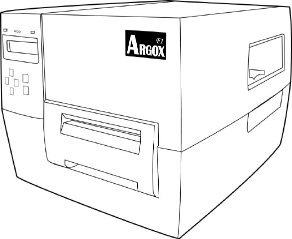
A LETTER TO OUR CUSTOMERS Dear Customer, Congratulations on selecting the Argox F Series label printer! You have made an excellent choice. This manual is intended to help you get to know your new printer. There are two parts: an operation guide and a technical reference. In the operation guide there are illustrations to help you quickly learn the functions and features of the printer. Information in greater detail is included in the latter chapters on troubleshooting, maintenance and technical reference.
CONTENTS INTRODUCTION ................................................................................................................................... 3 PRINTER OVERVIEW ............................................................................................................................. 3 Front View ..................................................................................................................................... 3 Rear View ......................................................
PERFORMING CALIBRATION ................................................................................................................ 45 PRINTING A CONFIGURATION LABEL .................................................................................................. 45 SELECT OR ADJUST THE MEDIA SENSOR ............................................................................................. 47 Select the See-through Sensor ...............................................................................
INTRODUCTION Congratulations on choosing the Argox F Series industrial barcode printer! This user’s manual, which describes the F-Series printer, will help you get to know your new printer. This manual includes a guide to operating the printer as well as related information on maintenance, troubleshooting and technical reference.
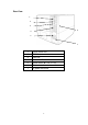
Rear View 1 2 3 6 4 5 7 1 RS232 Serial Port 2 PS/2 Port 3 USB Port 4 Centronics Parallel Port 5 Power switch (O = Off, I = On) 6 Electronics cover 7 AC power connector 4
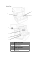
Interior View 2 1 3 4 5 6 7 1 Ribbon take-up spindle 2 Media supply hanger 3 Media roll guide 4 Print head module 5 Ribbon supply spindle 6 Media guide 7 Platen roller 5
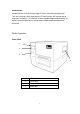
Control Panel All controls and indicators are located on the control panel. The LCD shows the operation status and printer parameters. The control panel buttons are used to operate the printer and to set parameters. The LED indicators show the printer’s operation status or indicate which control panel buttons are active.
Control Panel Buttons The printer has six basic control buttons on the control panel. Some of these buttons also work as selection keys. The selectable modes and related functions of the printer key are detailed below. Ready Mode Button Function / Description MENU Enter and exit Setup mode. Press for more than 5 seconds to enter special menu. LEFT The CANCEL key pauses printing.
Control Panel Lights Light POWER ALERT Status Function / Description On The printer power is turned on. Off The printer power is turned off. Blinking ALERT blinks when an error occurs.
Printer Setup Unpack and Inspect the Printer After unpacking the box, check to make sure you have the following items. Printer Power cord An extra ribbon core Ribbon core adaptor Media hanger USB cable CD-ROM Quick Installation Guide Note: If there are any items missing or damaged, please contact your reseller or distributor.
Placing the Printer Before setting up and connecting the printer, please consider the following: Find a solid surface that is large and sturdy enough to accommodate the printer. Choices could include a table, countertop, desk, or cart. This printer is designed to function in a wide range of environmental and electrical conditions. Please make sure to clear the ground and isolate the power adapter from other electrical cables. Isolate the power cord from other electrical cables.
Selecting a Communication Interface This printer comes with a USB interface, a standard Centronics parallel interface, and a nine-pin Electronics Industries Association (EIA) RS-232 serial data interface. USB Interface Requirements The Universal Serial Bus (USB) interface is version 2.0 and 1.1 compliant and provides a full-speed (12Mb/s) interface that is compatible with your existing PC hardware. The USB’s ―plug and play‖ design makes installation easy. Multiple printers can share a single USB port/hub.
RS-232 Serial Port USB Port Centronics Parallel Port Notes: 1. The Centronics port allows a much higher communication speed than the serial port. 2. The pin assignment of the cable used for this serial port is different than serial cables used for a PC. Please contact your local Argox reseller if you need this cable.
Communicating with the Printer The bundled printer driver can be applied to all applications under Windows 98/2000/2003/Windows XP and Windows Vista. With this driver you can run any popular Windows software applications such as MS-Word and print to this printer. Before installation 1. Check the contents of the driver to ensure it is completed. 2. Make a backup copy of the driver. Installing the Driver (Label Dr.200) 1. Double click the driver file (Label Dr. 200) to execute in Windows. 2. Click "Next".
4. Select the port of the printer and click "Next". 5. When the related files have been copied to your system, click ―Next‖. 6. After the installation is complete, click ―Finish‖. 7. Click ― Yes‖ to restart your computer.
Notes: 1. If you are updating the driver, make sure the previous version has been removed. 2. If you install new bar code application software such as ArgoBar, LabelView or CodeSoft, you should activate the Label Dr. 200 driver and set it as the current printer driver. 3. If you install new bar code application software such as Bartender Ultra Lite, you should activate the seagull driver for Argox printers.
Installing the Printer Driver (Seagull Driver) 1. Double click the driver file to execute in Windows. 2. Click "Next". 3. Select ‖Install printer drivers‖ and click ―Next‖.
4. Select a driver for your printer and click "Next" . Please select ―Argox F1 PPLB‖. 5. Select the port of the printer and click "Next.
6. Enter a specify Printer Name ―Argox F1 PPLB‖ and click ―Next‖ 7. Click ―Finish‖ to complete the installation.
8. After the related files have been copied to your system, click ―Finish‖ 9.
Notes: 4. If you are updating the driver, make sure you remove the previous version first. 5. If you install new bar code application software such as ArgoBar, LabelView or CodeSoft, you should activate the Label Dr. 200 driver and set it as the current printer driver. 6. If you install new bar code application software such as Bartender Ultra Lite, you should activate the seagull driver for Argox printers.
Installing USB Driver (Windows 98 Only) Note: Uninstall the printer driver before installing the USB driver. 1. Connect the label printer to a computer with a USB cable. 2. Turn on the printer’s power. 3. The window ―Add New Hardware Wizard‖ will pop, click ―Next‖. 4. Select ‖Search for the best driver for your device. (Recommended)‖, click ―Next‖. 5.
6. Click ― Next‖ 7. Click ― Finish‖ 8. Click ― Next‖ Note: After the USB driver is installed, you could refer to next page to install the printer driver.
Installing Printer Driver (Windows 98 Only) 9. Select‖ Search for the best driver for your device‖ ( Recommended)‖. 10. Click‖ Next‖ 11. Select‖ Specify a location‖ 12. Click‖ Browse‖ and choose Label Dr. 200 location. 13. Select― Win98‖ 14.
15. Click‖ Next‖ 16. Click‖ Next‖ 17. Click‖ Finish‖ 18.
19.
USB Plug and Play Function Note: The printer driver needs to be installed with version 1.4.00 or later and support ―USB Plug and Play‖ for Windows XP, Windows 2003 and Windows 2000. 1. Extract the PrinterDriver.exe to the fixed route. (―C:\Label Dr. 200‖, for example) 2. Connect the label printer to a computer with an USB cable. 3. Turn on the printer’s power and the system will detect the device automatically. 4. Select ―Install from a list or specific location (Advanced)‖, click ―Next‖.
5. Select ―Search for the best driver in these locations‖ and choose ―Include this location in the search‖. Input the location of the printer driver, click ―Next‖. 6. Select ―Continue Anyway‖.
7. Click ―Finish‖. 8. The Label Dr. 200 (4 inch model) printer is added in ―Printers and Faxes‖. 9. Reboot the system. 10. The system assigns the USB port for Label Dr. 200 (4 inch model) printer.
Installing the USB Driver in Windows Vista (Plug and Play) 1. Extract the PrinterDriver.exe to the fixed route. (―C:\Label Dr. 200‖, for example) 2. Connect the label printer to a computer with an USB cable. 3. Turn on the printer’s power and the system will detect the device automatically. 4. Select ―Locate and install driver software (recommended)‖. 5.
6. Select ―I don’t have the disk. Show me the other options.‖ 7. Select ―Browse my computer for driver software (advanced) ―.
8. Input the location of printer driver. (―C:\Dr200 Printer Driver_ x86\Win Vista\4 inch mode‖, for example) 9. Select‖ Install this driver software anyway‖ 10. The related files start to copy to your system.
11. After the installation is complete, click ―Close‖.
Operations Loading a Ribbon Note: The F-Series printer uses transfer thermal printing and the required ribbon is coated outside. 1. Lift the top cover and front access door to expose the media compartment. (Figure 1) Figure 1 2. Unlatch the print head module by pushing the release lever on the right side toward the rear.
Media Compartment Release Lever Figure 2 Print Module Figure 3 3. Unwrap the ribbon roll pack and separate the ribbon roll and the bare core. 4. Attach the edge of the ribbon to the bare core and wind a little bit onto the core.
Figure 5 5. Insert the ribbon roll into the supply holder. First snap in the right side and then left side. Make sure the coating side of the ribbon is face down. (Figure 6) Ribbon Supply Holder Figure 6 6. Put the print head module down and insert the bare core into the pick-up holder. (Figure 7-1) First snap in the right side and then left side.
7. Turn the wheel of the print head module to ensure the ribbon is tightly wound. (Figure 8) Wheel Figure 8 8. Press down the print head module firmly on both sides till you hear a snap.
Loading Media The F-Series printer offers three different loading modes: standard, peel-off, or with a cutter. Standard mode allows you to collect each label freely. Cutting mode automatically cuts the label after it prints. Peel-off mode peels backing material away from the label as it prints. After the label is removed, the next label prints. Standard Mode 1. Lift the top cover and front access door to expose the media compartment. 2.
4. Unlatch the print head module by pushing the release lever on the right side toward the rear. 5. Hold the print head module upward to let the media pass under it. Lead the media through the media guides with the other hand. Adjust the media guide to the media width by pushing the button located on the media guide. (Figure 11) Figure 11 6. Lead the media over the platen roller.
7. Close the print head module and then press it down firmly on both sides till you hear a snap. (Figure 13) Figure 13 8. Close the top cover and press the FEED button if the printer is already on. (Figure 14) Note: After the media is loaded, you could press FEED button to calibrate the media length.
Cutting Mode Note: For cutting mode you must first install the cutter—please refer to Appendix A. Follow steps 1 to 6 in ―Loading Media – Standard Mode‖ above and then continue with the steps below. 7. Thread the media over the platen roller, and then route the media through the slot of the cutter module. (Figure 15) Figure 15 8. Press down the print head module firmly. 9. Turn on the printer or press the ―FEED‖ button if the printer is already on.
Figure 16 Note: The ―FEED‖ button does not make the printer cut. For cutting to occur the panel setting must be properly enabled.
Peel Off Mode Note: 1. For Peel-off mode you must first install the dispenser kit. Please refer to Appendix B. Open the peeler assembly. (Figure 17) Figure 17 2. Remove approximately 6-inches of labels from the backing paper.
Figure 18 3. Lead the backing paper over the platen roller, and then thread it back into the slot. Make sure that the media is under the peeler module.
4. Close the peeler assembly. (Figure 20) Figure 20 5. Latch the print head module. 6. Close the top cover and turn on the printer or press the ―FEED‖ button if the printer is already on. (Figure 21) Figure 21 Note: The ―FEED‖ button does not make the printer peel. For peeling to occur the panel setting must be properly enabled.
Configuration This section discusses calibration, printer configuration settings and shows you how to view or change printer parameters through the control panel. Performing Calibration After the media is loaded, you should perform a media calibration to calibrate the media sensor. During the calibration, the printer determines the label length and the sensor settings. The results of the auto calibration are stored in the printer’s memory and are retained even when the printer power is off.
PRINTER CONFIGURATION VERSION INFORMATION: PPLB F1B0-1.00 . . . . . . . 032408 . . . . . . . . . . . . . . . 80320001 . . . . . . . . . . . . . 1.1 . . . . . . . . . . . . . . . . . . FIRMWARE VERSION DATE CODE (mmddyy) SERIAL NO EEPROM VERSION MEMORY INFORMATION : 8192 KB . . . . . . . . . . . . . 6088 KB . . . . . . . . . . . . . 4096 KB . . . . . . . . . . . . . 3071 KB . . . . . . . . . . . . . ONBOARD . . . . . . . . . .
Select or Adjust the Media Sensor This printer uses two types of media sensors: See-through and reflective. The default is see-through sensor No 1. Select the See-through Sensor The standard see-through sensor is in a fixed position and enabled from the control panel. (Figure 23) Figure 23 Adjust the Reflective Sensor 1. Press down the Thermal Print Head (TPH) release lever to release the print head module. 2. Lift the print head module to expose the media sensor cover. (Figure 24) 3.
Adjust Print Head Pressure If printing quality is not even, you may need to adjust the print head pressure. To adjust print head pressure use a flat tip screwdriver to turn the left and right screws counterclockwise to increase the pressure, or clockwise to decrease the pressure. (Figure 26) Left Screw Right Screw Figure 26 Adjust the pressure adjustment screws as follows: Condition Resolution Print quality of the left side of a label Turn the left screw counterclockwise to is too light.
Setup Mode You can set printer parameters for your application directly by using the control panel LCD and buttons. Enter Setup Mode 1. 2. Press
Password Parameters The F-Series printer has three password levels. When you enter the setup mode on the control panel, parameters which are not protected by password are displayed. You must enter a correct password to enter AUTHORISED SETUP 1 and AUTHORISED SETUP 2. The password levels and default passwords are shown in the following table.
Menu System The menu system lets you set printer options using the buttons on the control panel. The following is a description of menu selections and settings. Basic Setup Press
1 (CENTER) Sensor 1 is positioned in the center of the media route. This option enables sensor 1. 2 (LEFT) MEDIA CAL LENGTH 12 INCH (1~30) The position of sensor 2 is to the left side of sensor 1. This option enables sensor 2. Set the maximum label length to calibrate. The default media calibration length is 12 inches. MEDIA CALIBRATION Calibrate and detect media gap. Press to activate this operation. PRINT MODE Setup label removal method.
ROTATE CUTTER This parameter allows you to rotate cutter. Press to activate. Note: The parameter shows only if a cutter is installed. OFFSET This option fine tunes the media stop location TEAR OFFSET 0mm (-3~+3) Sets label tear off offset. PEEL OFFSET 0mm (-16~+16) Sets label peeling offset. CUT OFFSET Sets label cutting offset. 0mm (-16~+16) VERTICAL 0mm (-30~+30) Change the vertical position of the whole label format.
to scroll through the selection. Press to begin print out. SETTING Prints a printer configuration label. FORM LIST Prints a label that lists the form currently stored in the printer. GRAPHIC LIST Prints a label that lists the graphics currently stored in the printer. FONTS LIST Prints a label that lists the fonts in the printer. Authorised 1 FLASH MODULE ONBOARD Select flash memory module. Press the up <↑> and down <↓> buttons to scroll through the selection.
2. 3. Press and use the up <↑> and down <↓> buttons to scroll through selections. Press again and a warning message ―Are you sure‖ appears. You can select ―YES‖ to continue or ―NO‖ to cancel this operation. FORM Delete form. GRAPHIC Delete graphic. FONT Delete font. AUTO FORM Auto form lets you detach the printer from a computer and print in standalone mode. OFF Enable automatic form printing. ON Disable automatic form printing.
HEX DUMP The hex dump mode is a troubleshooting tool for checking the interconnection between the printer and the host computer. Select ―ON‖ and all transmitted data is dumped and printed as ASCII and Hex values. OFF Normal operating mode. ON Prints raw ASCII data received from the host. SERIAL COMM. Baud Rate 9600bps Sets serial port communication. Determines the RS-232 baud rate. The default baud rate is 9600bps.
0 (0~4ips) LOAD DEFAULT The default of base speed is 0. Reset Printer and panel settings. Press and a warning message ―ARE YOU SURE? YES/CONFIRM‖ appears. Select with the up <↑> and down <↓> buttons. Press to confirm. Authorised 2 RTC SETUP This function appears on the LCD display only when the RTC module is installed. Press and press the right <→> button to move to the next digit. Use the up <↑> and down <↓> buttons to select a value. Press to accept the value.
IGNORE COMMAND Set panel commands to be active or ignored. In default, all commands are active. SELECT ALL DARKNESS SPEED RIBBON DETECT MEDIA TYPE PRINT MODE PRINT WIDTH SERIAL COMM. RTC SETUP Special Setup LANGUAGE The LANGUAGE parameter is included in the special menu. You can select a language via the control panel. 1. Press
you to enter the old password. 4. 5. Press again and the printer prompts you to enter the new password. Press
Maintenance Argox recommends using following material to clean the printer: 100% ethanol Cotton swab Blower brush CAUTION! 1. The print head gets hot and could cause severe burns. Always allow the print head to cool before maintenance. 2. Argox is not responsible for damage caused by the use of cleaning fluids on this printer. Component Procedure Frequency Print head 1. Open the print head and remove the media and ribbon. 2. Using the swab and 100% ethanol, wipe the print head from end to end.
Troubleshooting This section provides information about errors that you might need to troubleshoot. If an error condition exists with the printer, review the LCD display error messages below for possible causes and the solutions. Error Messages LCD Display Blinking Buzzer LED Possible Cause Solution alert HEAD OPEN ALERT YES The print head is not fully closed. Close print head completely. RIBBON OUT ALERT YES Ribbon is not loaded or is incorrectly loaded. Load ribbon correctly.
Technical Reference General Specifications Model name F1 Printing method Direct Thermal / Thermal Transfer Printing resolution 203 dpi (8 dots/mm) Printing speed 2 ~ 6 ips (50 ~152 mm/s) Printing length 0.5‖ ~ 90‖ (13mm ~ 2286mm), MAX 90‖(Command mode) Printing width Max 4.
Code 93 EAN-13 EAN-13 2 digit add-on EAN-13 5 digit add-on EAN-8 EAN-8 2 digit add-on EAN-8 5 digit add-on Codabar Postnet UPC-A UPC-A 2 digit add-on UPC-A 5 digit add-on UPC-E UPC-E 2 digit add-on UPC-E 5 digit add-on GS1 Data Bar 2D Barcodes PPLB: Maxicode PDF-417 Data Matrix (ECC 200 only) QR code Composite code Fonts Internal character sets standard 5 alpha-numeric fonts with height from 0.049‖~0.
Bartender/ Font Utility Media Roll-feed, die-cut, continuous, fan-fold, tags, thermal ticket, plain paper and fabric label Max width 4.3‖ (110 mm) Min width 0.79‖ (20 mm) Thickness .0025‖~. 01‖ (.0635mm ~. 254mm) Max OD 8‖ (203 mm) ID width 1‖ and 3‖ (25.4mm~76 mm) (3‖ ID can be installed by media core adapter) Ribbon Wax, Wax/Resin, Resin(Ribbon wound ink-side out or ink-side in available) Ribbon width – 1.‖~ 4.3‖ (25.4mm ~ 110mm) Ribbon roll – max OD 2.
Interface Specifications The Argox F-Series printer sends and receives messages through serial, parallel and USB communication interfaces. The printer automatically checks each interface for incoming messages. Serial Interface Specification The serial interface of the F-Series printer is an RS-232 port with 9-pin (DB9-S) connector located at the rear of the printer. You can change the baud rate; data bit, parity bit and stop bit by both sending commands to the printer and by using the LCD panel.
Parallel Interface Specification The parallel interface of the F-Series printer is a Centronics port with standard 36-pin connector located at the rear of the printer. You can connect the F-Series printer and the host controller with a standard parallel cable. . Pin Assignment and Description Pin No. Direction Description Pin No. Direction 1 IN /STROBE 13 OUT SELECT 2 IN DATA 1 14,15 ----- N.C. 3 IN DATA 2 16 OUT GROUND 4 IN DATA 3 17 OUT GROUND 5 IN DATA 4 18 ----- N.C.
PS2 Keyboard Interface The Argox F-Series printer provides a standard IBM PC PS2 keyboard interface that lets you control the printer with a standard PS2 keyboard. Pin Assignment and Description The PS2 keyboard interface is a female, 6-pin, mini DIN connector. Pin No. Direction Description 1 ----- N.C. 2 OUT +5V 3 ----- N.C. 4 IN/OUT DATA 5 GROUND 6 IN/OUT CLOCK USB Interface The Argox F-Series printer provides a standard USB interface that conforms to USB 2.0 full-speed specification.
Appendix A: Stand-alone Keyboard & Barcode Reader This appendix covers stand-alone operation with keyboard or barcode reader. Keyboard To use the printer in stand-alone operation with a keyboard, please follow the procedure described below: 1. 2. Press the MENU key to enter menu mode on the LCD panel. Enter a password to switch to privileged menu and enable the AUTO 3. 4. 5. 6. 7. 8. 9. FORM function. Save the changes and press MENU again to leave the settings menu. Make a form for the keyboard.
Insert Inserts a new character at the cursor position. Shift Switches between upper/lower case characters as the shift key is pressed. Delete Deletes the character at the cursor and shifts all the characters on the right forwards. Caps Lock Switches to upper case characters. Space Moves the cursor to right. Home Moves the cursor to the leftmost position. End Moves the cursor to the rightmost position. Example: Stand alone operation with keyboard form Please follow the procedure below: 1.
4. Turn off the printer, connect the keyboard and then turn on the printer. 5. The LCD displays this message: SELECT FORM KBDFORM 6. 7. Use the up and down keys to select another form and press to confirm. Once a form is selected, the LCD displays: LOADING FORM KBDFORM 8. Key-in the input device and barcode data. Product Name? Barcode Printer Product No. ? 0123456789 9. Input the label count and the copy count. LABEL SET NO. ? 2 COPIES PER LAB. ? 3 10.
Output 71
Barcode Reader Example: Stand alone operation with READER form Please follow the procedure below: 1. Make a command file for the form, READER.FRM 2. 3. 4. 5. Command Description ZS FK"READER" FS"READER‖ Enable store to flash Delete previous form Start of form V00,15,N,"Product Name ?" C0,10,N,+1,"Product No.
6. A label is printed. The copy count depends on the PA command for the READER form. Step 4 repeats automatically. Output Notes: 1. 2. 3. To return to normal operation, press and hold on keyboard or the CANCEL key for more than 5 seconds. During standalone operation, you can input data through: Keyboard Barcode reader Parallel port Serial port USB For the keyboard form the P command is not allowed, while for the barcode reader/ scanner form, a PA command must be included.
Appendix B: Cutter Installation Follow this procedure to install a cutter in the printer. 1. Turn off the printer. 2. Remove the left cover and press down the TPH release lever to release the print head module. 3. Locate the cutter in the two slots and secure two screws indicated in the figure below. 4. Turn on the power switch and enable the cutter from the control panel. Installing Media and Ribbon with Cutter The first time after installation or after a cutter jam use the following procedure: 1.
All other times use the following procedure: 1. 2. 3. 4. Put the media end on the roller. Close the TPH latch. Turn on the printer. Press the FEED button so the media end goes through the cutter. The cutter generally cuts the label at the center of the media gap. You may change the cutting position for special media by operating the panel setting or sending a shift command to the printer: Panel setting: 1. 2. 3. 4. 5. Enter the panel setting menu and choose OFFSET item.
Appendix C: Dispenser Installation 1. 2. 3. 4. Turn off the printer Remove the left cover and press down the TPH release lever to release the print head module. Screw the peeler brace to the printer as shown in the figure below. Turn on the power switch and enable the peeler function from the control panel.
Appendix D: Super card Installation 1. Shut the power down and open the back cover. 2. Plug the super card in the socket and set the DIP switch 5 to ON. 3. Turn on the power and wait the LCD display appears ―RESTART PRINTER‖. Note: When you un-plug the super card, please shut the power down and put the DIP switch 5 to OFF.