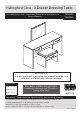
Hallingford Gloss - 3 Drawer Dressing Table Assembly Instructions - Important: Retain these instructions for future reference 796/4699 764/5554 CR CR CR WARNING! In order to prevent overturning, this product must be used with the 2 wall attachment devices provided Dimensions Width - 119.9cm Depth - 41.1cm More help is available throughout this booklet by scanning in the QR codes or typing in the links Height - 79.
Safety and Care Advice Important - Please read these instructions fully before starting assembly • Warning: This unit weighs approximately 44kgs. Please lift with care. • Assembly to be carried out by a competent adult only. • Check you have all the components and tools listed on pages 1 to 3 for the Dressing Table and pages 22 to 23 for the Stool. • Remove all fittings from the plastic bags and separate them into their groups.
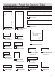
Components - Panels for Dressing Table Please check you have all the panels listed below 5 Top Modesty (DF-00018002) (115.9 x 19.2cm) 2 6 Bottom Modesty (DF-00018013) (115.9 x 19.2cm) 3 Left Side (DF-00013110) (76.7 x 39.4cm) 4 Right Side (DF-00013111) (76.7 x 39.4cm) Mirror - MIR-00000011 (54.8 x 48.4cm) Safety Back SAR 7 Left Divider (DF-00018004) (16.7 x 35.75cm) 8 Right Divider (DF-00018005) (16.7 x 35.75cm) 9 Mirror Back (DF-00018003) 10 Left Drawer Front (DF-00018045) (33 x 16.
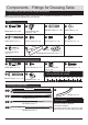
Components - Fittings for Dressing Table Please check you have all the fittings listed below Note: The quantities below are the correct amount to complete the assembly. In some cases more fittings may be supplied than are required.
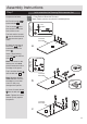
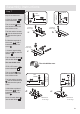
Assembly Instructions Step 1 Let’s assemble the Dressing Table carcase first Prepare the left side a: Fit a CL runner to the left side 3 . Fixing Bottom Mounted Runners https://www.youtube.com/watch?v=Z6lGMy19h7Q O a Finished front edge The 1st screw G uses the 1st hole in from the front of the runner. G The 2nd and 3rd screws .G use the holes that line up with the other panel holes. G Finished front edge a: Insert 2 large locking cam nuts B into the left side 3 .
Assembly Instructions Step 2 Prepare the top modesty and bottom modesty C B B C Tap 4 wooden dowels C into the top modesty 5 and the bottom modesty .6 . 5 B B B Insert 4 large locking cam nuts B into the top modesty 5 and the bottom modesty 6 . C B C C Finished front edge B 6 B C Push the top and bottom modesty panels 5 and . 6 down onto the left side 3 . Use a screwdriver to tighten the 2 large locking cam nuts B fitted to each modesty panel 5 and 6 .
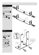
Assembly Instructions Step 4 Prepare the right side O b a: Fit a CR runner O b to the right side 4 . CR G The 2nd and 3rd screws .G use the holes that line up with the other panel holes. G G R C The 1st screw G uses the 1st hole in from the front of the runner. a: O b 4 Finished front edge b: Mark the top hole of the runner O b with a bradawl and then fit a screw F . B B Insert 2 large locking cam nuts B into the right side 4 .
Assembly Instructions Step 5 Note: Support the right side until you lay the assembly down in the next step. Fit the right side Push the right side 4 down onto the modesty panels 5 and 6 . 4 Use a screwdriver to tighten the 2 large locking cam nuts B fitted to each modesty panel 5 and 6 . 5 6 L C Step 6 Carefully lay the unit down onto its back. Warning: The unit is heavy. Lift with care.
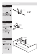
Assembly Instructions Step 7 O a to the left divider 7 . The 1st screw G uses the 1st hole in from the front of the runner. O a CL G G Finished front edge O a O a F b: 7 L C a: Finished front edge G L C The 2nd and 3rd screws .G use the holes that line up with the other panel holes. Finished front edge a: Fit a CL runner Finished front edge Prepare the left divider Bradawl 1st screw G 7 b: Mark the top hole of the runner O a with a bradawl and then fit a screw F .
Assembly Instructions Step 8 Prepare the 2 small cross rails B C B Tap 2 wooden dowels C into each of the 2 small cross rails 2 . Finished front edge x2 2 Insert 2 large locking cam nuts B into each of the 2 small cross rails 2 . C Step 9 Fit a small cross rail to the left divider Finished front edge 2 7 R C Push a small cross rail 2 down onto the left divider 7 . Finished front edge Use a screwdriver to tighten the large locking cam nut B fitted to the small cross rail 2 .
Assembly Instructions Step 11 The 1st screw G uses the 1st hole in from the front of the runner. CR G 8 b: Mark the top hole of the runner O b with a bradawl and then fit a screw F . Finished front edge 8 Finished front edge B B C C c: 8 R Insert 2 large locking cam nuts B into the right divider 8 . b: O b F C c: G R C a: G O b R C The 2nd and 3rd screws .G use the holes that line up with the other panel holes. O b Finished front edge Fit a CR runner O b to the right divider 8 .
Assembly Instructions Step 12 Fit a small cross rail to the right divider Finished front edge 2 L C Push a small cross rail 2 down onto the right divider 8 . Finished front edge 8 Use a screwdriver to tighten the large locking cam nut B fitted to the small cross rail 2 . Step 13 CL Fit the small cross rail and right divider CL Finished front edge Push the small cross rail . 2 onto the right side 4 . CL Use a screwdriver to tighten the large locking cam nut B fitted to the small cross rail 2 .
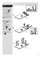
Assembly Instructions Step 15 Finished front edge Fit the top CL Push the top 1 onto the assembly. CL Use a screwdriver to tighten the 8 large locking cam nuts B fitted to the left side 3 , right side 4 , left divider . 7 and right divider 8 . 3 7 1 8 CL 4 Step 16 Fit the 4 plastic nails CL CL Tap 2 plastic nails D into the bottom edge of each of the sides 3 and .4 . 3 D CL D Carefully stand the unit up for the next step. Warning: The unit is heavy. Lift with care.
Assembly Instructions Step 17 Warning: Glass! Handle with care Fit the mirror back From the front of the unit, push the 2 connecting sleeves I through the holes in the top modesty . 5 and then locate them into the holes in the mirror back 9 . 9 H H CR 5 From the rear of the mirror back 9 , insert the screws H into the connecting sleeves I and firmly tighten them up.
Assembly Instructions Step 19 Fit the 2 overbalance protector kits To prevent possible overbalancing this unit must be secured to a suitable wall by fitting of the 2 overbalance protector kits J to the unit WARNING! In order to prevent overturning this product must be used with the 2 wall attachment devices provided Example l Wall fixings are not supplied as they will need to suit the wall type.
A Guide to Wall Mounting & Fixings Important: When drilling into walls always check that there are no hidden wires or pipes etc. Important note: If plastic wall plugs are supplied with your product: Make sure that the screws and wall plugs being used are suitable for supporting your unit. Consult a qualifed tradesperson if you are unsure. Hints: - these are only suitable for use in masonry walls. If you are in any doubt about the correct wall plugs for your wall, seek professional advice.
Assembly Instructions Step 20 Prepare the left and right drawer fronts Screw 2 metal dowels A into both the left drawer front 10 and the right drawer front 11 . Now assemble the drawers for the Dressing Table Drawer Assembly www.youtube.com/watch?v=InNBV_uuMmo A A A Note: The small right drawer front has a small identification hole. A A Note: Tighten the metal dowels up fully against the panels.
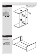
Assembly Instructions Step 23 Fit the deep drawer bases x2 15 13 4 Slide the deep drawer base 15 down into the grooves in the deep drawer sides 12 and 13 and down into the groove in the left drawer front 10 and right drawer front 11 . 12 10 11 Step 24 Fit the deep drawer backs Fit the deep drawer back .14 between the deep drawer sides 12 and 13 . Make sure that the deep drawer base 15 fits into the groove in the deep drawer back 14 .
Assembly Instructions Fixing Bottom Mounted Runners https://www.youtube.com/watch?v=Z6lGMy19h7Q Step 27 Fit runners to the drawers Bradawl Runners must be pushed up against the drawer front Fit the DL runner O c to the bottom edge of the left drawer side 12 , as shown, making sure that it is pushed up against the back of the drawer front 10 and 11 . Use a bradawl to mark the fixing positions, then secure with 2 screws F .
Assembly Instructions Step 30 Attach the narrow drawer sides to the centre drawer front Push the narrow left drawer side 17 and narrow right drawer side .18 onto the back of the centre drawer front 16 . K 18 17 16 A B Turn the small locking nuts K on the narrow left drawer side 17 and narrow right drawer side .18 . Step 31 Fit the narrow drawer base Slide the narrow drawer base 20 down the grooves in the narrow drawer sides 17 and 18 and down into the groove in the centre drawer front 16 .
Assembly Instructions Step 33 Important: Make sure that the drawer assembly is square before fitting the wedgefixes. Fit the wedgefixes Turn the narrow drawer assembly over and slide 2 wedgefixes N into the front and back grooves, as shown, and tighten up the screws.
Assembly Instructions Step 35 Fit the drawers Fixing Bottom Mounted Runners h�ps://www.youtube.com/watch?v=Z6lGMy19h7Q Panel Slide the wheels of the runners fitted to the drawers, over the wheels of the runners fitted to the side panels and push the drawers into position.
Components - Panels for Stool If you need help or have damaged or missing parts, please visit www.argos-support.co.uk or email: Help@ClickSpares.co.uk (quoting your original order number) Alternatively, call the Spares Helpline on: 0370 112 1928. For any other queries please contact the Customer Helpline on: 0345 640 2020 Please check you have all the panels listed below 21 Stool Left Side (DF-00013090) (39.6 x 34.9cm) 24 Stool Cross Rail (DF-00013089) (46.
Components - Fittings for Stool If you need help or have damaged or missing parts, please visit www.argos-support.co.uk or email: Help@ClickSpares.co.uk (quoting your original order number) Alternatively, call the Spares Helpline on: 0370 112 1928. For any other queries please contact the Customer Helpline on: 0345 640 2020 Please check you have all the fittings listed below Note: The quantities below are the correct amount to complete the assembly.
Assembly Instructions Step 37 Let’s assemble the Stool carcase Prepare the stool left side Fitting Ball Bearing Runners www.youtube.com/watch?v=yG4x�JJeSg a: Place a runner R on the stool left side 21 as shown. Slide back the top of runner and use the 2nd hole from the front to fit the 1st screw G . G R b: Slide the runner back the other way and fit the 2nd screw G into the corresponding hole in the stool left side 21 . c: Screw 4 metal dowels G R A a: 21 into the stool left side 21 .
Assembly Instructions Step 38 G Prepare the stool right side R a: Place a runner R on the stool right side 22 as shown. Slide back the top of runner and use the 2nd hole from the front to fit the 1st screw G . R a: b: Slide the runner back the other way and fit the 2nd screw G into the corresponding hole in the stool right side 22 . c: Screw 4 metal dowels 22 A G into the stool right side 22 . D: Insert 2 large locking cam nuts B into the stool right side 22 .
Assembly Instructions Step 39 Prepare the 2 stool back rails B B C B Tap 2 wooden dowels C into each of the 2 stool back rails 25 . 25 x2 Insert 4 large locking cam nuts B into each of the 2 stool back rails 25 . Step 40 B C The top edge of the stool back rail must be flush with the top edge of the left side Fit a stool back rail to the stool right side 25 Push a stool back rail 25 down onto the stool right side 22 .
Assembly Instructions Step 43 Fit the 2 stool cross rails Finished front edge 24 Push the 2 stool cross rails 24 down onto the stool right side 22 . 24 Finished front edge 22 Step 44 Fit the left side Push the left side 21 onto the assembly. 21 Use a screwdriver to tighten the 2 large locking cam nuts B fitted to each of the 2 stool back rails .25 . 25 25 Step 45 Fit the 4 plastic nails Tap 2 plastic nails D into the bottom edge of each of the sides 21 and .22 .
Assembly Instructions Step 46 A A Prepare the stool top A Screw 4 metal dowels A into the stool top 23 . A 23 Step 47 Fit the seat pad to the stool top Fit the seat pad 31 to the stool top 23 using 4 screws Q . Note: Make sure that you screw into the hard surface of the seat pad. 31 23 Q Q Q Soft surface Q Hard surface Step 48 Fit the stool top Push the stool top 23 down onto the stool sides 21 and 22 . Use a screwdriver to tighten the 4 large locking cam nuts B fitted to the stool sides .
Assembly Instructions Step 49 Now assemble the drawer for the Stool A Prepare the stool drawer front A Screw 2 metal dowels A into the stool drawer front 26 . 26 Step 50 K Prepare the stool drawer sides K 27 Insert a small locking cam nut K into the stool left drawer side 27 and stool right drawer side 28 . 28 Step 51 Attach the stool drawer sides to the stool drawer front Push the stool left drawer side 27 and stool right drawer side 28 onto the back of the stool drawer front 26 .
Assembly Instructions Step 53 Fit the stool drawer back Fit the stool drawer back .30 between the stool drawer sides 27 and 28 . Make sure that the stool drawer base 29 fits into the groove in the stool drawer back 30 . M M 30 28 29 M 27 M Hold the stool drawer back 30 in position and tap the knock-in pegs M through the holes in the stool drawer sides 27 and 28 . Step 54 Fit the handle L L Attach a handle P to the stool drawer front 26 using screws L .
Assembly Instructions Step 56 Fit the stool drawer Slide both the runners R forward and locate the drawer sides 27 and 28 between them, lining up the holes in the drawer wrap with the 2nd 'threaded' holes in the runners R . Working from the inside of the drawer, insert 2 screws H through the drawer sides and out into the 2nd threaded hole in the runner. Fitting Ball Bearing Runners www.youtube.