New Hallingford - 3 Drawer Bedside Assembly Instructions - Important: Retain these instructions for future reference 652/9482 618/4999 673/1902 620/9379 673/2176 601/6737 677/5449 618/6959 678/3699 616/9749 887/6449 916/0109 WARNING! In order to prevent overturning, this product must be used with the wall attachment device provided Dimensions Width - 37.
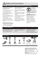
Safety and Care Advice Important - Please read these instructions fully before starting assembly • Warning: This unit weighs approximately 14kgs. Please lift with care. • Parts of the assembly will be easier with 2 people. • Assembly to be carried out by a competent adult only. • Make sure you have enough space to layout the parts before starting. • Check you have all the components and tools listed on pages 1, 2 and 3. • Do not stand or put weight on the product, this could cause damage.
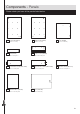
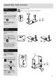
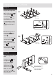
Components - Panels Please check you have all the panels listed below 1 Left Side (D2307A) 2 Right Side (D2308A) 4 Rail (D2310A) (34.1 x 6cm) x 2 5 Drawer Front (D2309A) (36.2 x 16.2cm) x 3 6 Left Drawer Side (W370-124LH) (37 x 12.4cm) x 3 7 Right Drawer Side (W370-124RH) (37 x 12.4cm) x 3 (55.6 x 37.2cm) 9 Drawer Base (T304-367) (30.4 x 36.7cm) x 3 (55.6 x 37.2cm) 3 Top (D2306A) (37.5 x 39.6cm) 8 Drawer Back (W291-124) (29.1 x 12.4cm) x 3 10 Back (X535-366) (53.5 x 36.
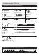
Components - Fittings Please check you have all the fittings listed below Note: The quantities below are the correct amount to complete the assembly. In some cases more fittings may be supplied than are required.
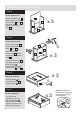
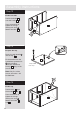
Assembly Instructions Step 1 Prepare the 3 drawer fronts Screw 2 metal dowels B into the holes shown on the back of each drawer front 5 . Drawer Assembly www.youtube.com/watch?v=3fYL5zB6ZYQ B B x3 B 5 Note: Tighten metal dowels up fully against the panels. Step 2 Prepare the drawer sides Insert a small locking cam nut C into the hole shown on the left drawer side 6 and right drawer side 7 . C C C 7 6 x3 Note: The arrow on the locking cam nut must point towards the hole in the edge of the panel.
Assembly Instructions Step 4 Fit the drawer base 9 Slide the drawer base 9 down the grooves in the drawer sides 6 and 7 and down into the groove in the drawer front 5 . x3 7 6 5 Step 5 E Fit the drawer back Fit the drawer back 8 between the drawer sides 6 and 7 . Make sure that the drawer base 9 fits into the groove in the drawer back 8 . E 8 E 7 E 9 6 x3 Hold the drawer back 8 in position and tap the knock-in pegs E through the holes in the drawer sides 6 and 7 .
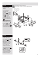
Assembly Instructions Fixing Bottom Mounter Runners https://www.youtube.com/watch?v=Z6lGMy19h7Q Step 8 Turn the 3 drawer assemblies over. Runners must be pushed up against the drawer front Fit runner K d , marked with ‘DR’, to the bottom edge of the right drawer side 7 , as shown, making sure that it is pushed up against the back of the drawer front .5 . Use a bradawl to mark the fixing positions, then secure with 2 screws I .
Assembly Instructions Fixing Bottom Mounter Runners https://www.youtube.com/watch?v=Z6lGMy19h7Q Step 10 Prepare the left side The 1st screw H uses the 1st hole in from the front of the runner. 1st screw H Finished front edge a: Fit 3 CL runners K a to the left side 1 . K a CL H Finished front edge H H H H H L C The 2nd and 3rd screws .H use the holes that line up with the other panel holes.
Assembly Instructions Step 11 Prepare the right side a: H H H H H H K b R C Fit 3 CR runners K b to the right side 2 . H H R C a: H R C K b 2 The 1st screw H uses the 1st hole in from the front of the runner. K b Finished front edge b: Mark the top hole of the runners K b with a bradawl and then fit a screw I . Finished front edge 1st H screw The 2nd and 3rd screws .H use the holes that line up with the other panel holes.
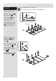
Assembly Instructions Step 13 Fit the left side 4 CR 1 CR Use a screwdriver to tighten the 2 large locking cam nuts D fitted to the rails 4 . CR Push the left side 1 onto the 2 rails 4 . 4 Step 14 N B Prepare the top Screw 2 metal dowels B into the top 3 . B N Fit the bracket from the overbalance protector kit .N to the shallow mark-hole drilled into the top 3 using 1 of its screws. 3 Shaped front edge Note: Only fit 1 of the screws, the other 1 will be fitted later.
Assembly Instructions Step 16 Squaring up a Chest and fitting the Back Panel www.youtube.com/watch?v=FeaI6541z7o Fit the back a: Square up the unit by making sure that measurement x to x equals y to y. b: Place the back a: The measurement from top corner X to bottom corner X must be equal to the measurement from top corner Y to bottom corner Y b: 10 onto the unit. x F Nail F around the outside edges of the back 10 . y CR Note: Nails should be spaced about 150mm apart.
Assembly Instructions Step 18 Secure the unit to a wall a: Before fitting the unit to a wall, use a spirit level to check the top of the unit is level, front-to-back and side-to-side in the 3 positions shown. Use suitable packing pieces (not supplied) to make the unit level. To prevent possible overbalancing this unit must be secured to a suitable wall by fitting the overbalance protector kit .N to a wall. b: Push the unit up against the wall and slide the bracket against the wall.
A Guide to Wall Mounting & Fixings Important: When drilling into walls always check that there are no hidden wires or pipes etc. Important note: If plastic wall plugs are supplied with your product: Make sure that the screws and wall plugs being used are suitable for supporting your unit. Consult a qualified tradesperson if you are unsure. Hints: - these are only suitable for use in masonry walls. If you are in any doubt about the correct wall plugs for your wall, seek professional advice.
Assembly Instructions Step 19 Fixing Bottom Mounter Runners https://www.youtube.com/watch?v=Z6lGMy19h7Q Fit the drawers Slide the wheels of the runners fitted to the drawers, over the wheels of the runners fitted to the side panels and push the drawers into position.
ALR2976