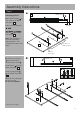
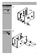
New Pagnell Desk 622/1168 Assembly Instructions - Please keep for future reference 618/7202 606/9447 Dimensions Width - 100cm Depth - 48.5cm Height - 71.
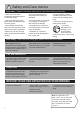
Safety and Care Advice Important – Please read these instructions fully before starting assembly • Check you have all the components and tools listed on the following pages. • Remove all fittings from the plastic bags and separate them into their groups. • Keep children and animals away from the work area, small parts could choke if swallowed. • Make sure you have enough space to layout the parts before starting. • Do not use this item if any components are missing or damaged.
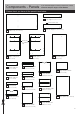
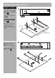
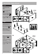
Components - Panels If you have damaged or missing components, call the Customer Helpline: Argos = 0345 6400800 Please check you have all the panels listed below 2 Top support (58.5 x 11cm) Finished front edge 3 Bottom support (58.5 x 11cm) 1 Table top (100 x 48cm) Pilot holes for guidance only 4 Right side panel (46 x 70cm) 7 Front support (36.7 x 11cm) 5 Middle panel 6 Left side panel (46 x 70cm) (46 x 70cm) 11 Drawer right side x 2 (34 x 11.5cm) 18 Large drawer back 8 Back support (36.
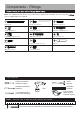
Components - Fittings Note: The quantities below are the correct amount to complete the assembly. In some cases mor may be supplied than are required.
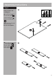
Assembly Instructions Step 1 a: Attaching runners a: Position Runners 4 Middle hole B A A front edge of the Right side panel 4 . in A Slide top of the Runners A . 1.7cm A B B A Runners A on the Right side panel 4 . B B Note: The front part of the runner should be approximately 1.7cm from the front edge of the panel. Pilot holes for runner position 4 Finished front edge b: Slide top of Runners forward and fix as shown using Screws B .
Assembly Instructions Step 1 - continued c: Position Runners in front edge of the Middle panel 5 . A c: Slide top of the Runners A . B 5 Middle hole A B 1.7cm B B Runners A on the Middle panel 5 . A A B Note: The front part of A the runner should be approximately 1.7cm from the front edge of the panel. Finished front edge 5 Pilot holes for runner position d: Slide top of Runners forward and fix as shown using Screws B .
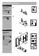
Assembly Instructions Step 2 Fitting dowels and locking pins a: Insert Dowels a: F into the Left side panel 6 . C Screw Locking pins F into the Left side panel C 6 . F C Note: Insert locking pins as far as shown. Do not over tighten. C F 6 b: Insert Dowels C into the Top support Bottom support Front support 7 Back support 8 , , and .
Assembly Instructions Step 3 Attaching plastic supports a: a: E E E D Plastic supports D onto the Front panel 9 . D E 9 D b: E b: Front panel 9 onto the Front support 7 . E E 9 E 7 Step 4 Attaching bottom panel and back support back edge G a: Position Front support 7 and Back support 8 onto the Right side panel 4 . G 4 Insert Locking nuts G into the Front support 7 and Back support 8 . 8 Use a screwdriver to turn Locking nuts G clockwise to lock.
Assembly Instructions Step 5 Attaching middle panel a: a: H Middle panel 5 onto the unit. back edge Use Screw covers I to cover the screw heads. 8 5 H H I 7 H H b: H Top support 2 and Bottom support 3 onto the Middle panel 5 .
Assembly Instructions Step 6 Attaching left side panel G Position Left side panel 6 onto the unit. G back edge 2 3 Insert 2 Locking nuts into the Top support 2 and Bottom support 3 . G Use a screwdriver to turn Locking nuts G clockwise to lock. Step 7 G 6 a: Attaching table top F F F F a: Screw Locking pins into the Table top 1 . F F F Note: Insert Locking pins as far as shown. Do not over tighten. b: Then carefully locate the Table top the unit.
Assembly Instructions Step 8 J Fixing back panel Attach Back panel 19 onto the unit using Nails J . 19 Important: The unit MUST be ‘square’ when back is attached. 8 1 4 5 Step 9 a: Drawer assembly F a: Screw Locking pins F F F into 4 holes shown on back of the Drawer front 10 . F F 10 Note: Insert Locking pins X2 as far as shown. Do not over tighten. b: Fix Drawer left side 12 onto the Drawer front 10 . b: 12 10 Continued on next page.
Assembly Instructions Step 9 - continued c: Fix Drawer right side 11 10 c: K 11 onto the Drawer front . Insert 2 Locking nuts K into the holes (they will only insert one way). 12 10 Use a screwdriver to turn Locking nuts K clockwise to lock. d: Insert 2 Locking nuts K into the holes (they will only insert one way). d: K 14 Use a screwdriver to turn Locking nuts K clockwise to lock. K 11 Place a small amount of Glue L into the grooves.
Assembly Instructions Step 10 a: Large drawer assembly a: Screw Locking pins F F F F F F 15 into 4 holes shown on back of the Large drawer front 15 . Note: Insert Locking pins as far as shown. Do not over tighten. b: 17 b: Fix Large drawer left 15 side 17 onto the Large drawer front 15 . c: Fix Large drawer right side 16 onto the Large drawer front 15 . c: K 16 Insert 2 Locking nuts K into the holes (they will only insert one way).
Assembly Instructions Step 10 - continued e: Place a small amount e: of Glue L into the groove on the Large drawer back 18 . f: Position the Large drawer back 18 onto the unit using Screws M . L L 18 M f: M 18 M 14 17 Step 11 Inserting large drawer a: With help, carefully stand desk upright. Warning: The Desk is heavy. Lift with care. a: Slide the drawer fully onto the runners so the runners butt up against the back of the drawer front.
Assembly Instructions Step 12 Inserting drawers a: a: Slide the drawer fully onto the runners so the runners butt up against the back of the drawer front. N b: Fix through drawer N sides into the runners using Screws N . N b: N 10 N 10 Step 13 Finishing the unit With help, place the unit in the intended position. Note: Before use allow the glue to dry for 24 hours and make sure the unit is secure. Assembly is complete.