New Pagnell 3 Dr 4 Drw Wardrobe 605/8788 Assembly Instructions - Please keep for future reference 617/6127 607/9884 Dimensions Width - 114.5cm Depth - 54.5cm Height - 180.
Safety and Care Advice Important – Please read these instructions fully before starting assembly • Check you have all the components and tools listed on the following pages. • Remove all fittings from the plastic bags and separate them into their groups. • Keep children and animals away from the work area, small parts could choke if swallowed. • Make sure you have enough space to layout the parts before starting. • Do not use this item if any components are missing or damaged.
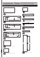
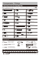
Components - Panels If you have damaged or missing components, call the Customer Helpline: Argos = 0345 6400800 Please check you have all the panels listed below 7 Shelf x 2 (49.8 x 36.7cm) 1 Top panel (114.6 x 54cm) Pilot holes for guidance only Finished front edge 8 Front bottom panel (111.2 x 11cm) 9 Back bottom panel (111.2 x 11cm) 2 Right side panel (179 x 52cm) Finished front surface 10 Front panel (111.2 x 7cm) Pilot holes for guidance only 11 Bottom support (111.
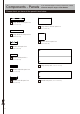
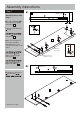
Components - Panels If you have damaged or missing components, call the Customer Helpline: Argos = 0345 6400800 Please check you have all the panels listed below 14 Large drawer front panel x 2 (72.4 x 14.5cm) 20 Large drawer bottom panel x 2 (70.7 x 33.6cm) 15 Large drawer back panel x 2 (69.8 x 11.5cm) 21 Drawer bottom panel x 2 (34.4 x 33.6cm) 16 Drawer front panel x 2 (36.1 x 14.5cm) 17 Drawer back panel x 2 (33.5 x 11.5cm) 22 Large back panel (173.2 x 75.
Components - Fittings Note: The quantities below are the correct amount to complete the assembly. In some cases mor may be supplied than are required.
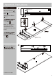
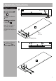
Assembly Instructions Step 1 a: 2 Middle hole A Attaching runners and hinges a: Position Runners A front edge of the Right side panel 2 . B in 1.7cm V V Slide top of the Runners A back. D E E C B Runners A on the Right side panel 2 . D C Note: The front part of the runner should be approximately 1.7cm from the front edge of the panel. 2 D A A C B D Finished front edge B D Door hinges C ‘back plates’ onto the Right side panel 2 .
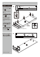
Assembly Instructions Step 1 - continued c: Position Runners c: in front edge of the Left side panel 3 . A Slide top of the Runner A back. 3 Middle hole B A 1.7cm D D B C Runners A on the Left side panel 3 . D Note: The front part of C C the runner should be approximately 1.7cm from the front edge of the panel. D C B 3 B D C back edge Door hinges ‘back plates’ onto the Left side panel 3 .
Assembly Instructions Step 1 - continued e: Position Runners e: B 4 Middle hole A in front edge of the Center panel 4 . A 1.7cm Slide top of the Runners A back. D D B C Runners A on the Center .panel 4 . E D C Note: The front part of the runner should be approximately 1.7cm from the front edge of the panel. C D 4 C B B D C D V Door hinges ‘back plates’ onto the Center panel 4 .
Assembly Instructions Step 1 - continued g: Position Runners g: 4 Middle hole in front edge of the Center panel 4 . A A Slide top of the Runners A back. B 1.7cm B Runners A onto the Center panel 4 . Note: The front part of the runner should be approximately 1.7cm from the front edge of the panel. 4 A A B Finished front edge B Pilot holes for runner position h: Slide top of Runners A forward and B h: Middle hole B B 4 A .
Assembly Instructions Step 2 Fitting locking pins F Screw Locking pins F into the Right side panel 2 , Left side panel 3 and Center panel 4 . Note: Insert locking pins as far as shown. Do not over tighten.
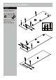
Assembly Instructions Step 3 G T G I Fitting dowels Insert Dowels G and Long dowel T into Right middle panel 5 ,Left middle panel 6 ,Front bottom panel 8 and Back bottom panel 9 . I Stop H onto the Right middle panel 5 . G 5 6 H G Finished front edge G Finished front edge G I G G Finished front edge H 9 8 G G Step 4 a: Attaching plastic supports a: K K K J J K K 10 J J K supports J K Plastic onto the Front panel 10 and Bottom support 11 .
Assembly Instructions Step 5 Attaching right middle panel Note: 2 people are need back edge at this stage. M Right middle panel 5 onto the Center panel 4 . 5 4 T M M 5 Step 6 Attaching front bottom panel M Front bottom panel 8 onto the Center panel 4 .
Assembly Instructions Step 7 Attaching back bottom panel M bottom panel 9 onto the Center panel 4 . 4 M 9 Step 8 Attaching back support Insert Dowels Back support G into 12 . G the Finished front edge 12 M support 12 onto the Center panel 4 .
Assembly Instructions Step 9 L Attaching right side panel Position Right side panel 2 onto the unit. Insert 5 Locking nuts L in the Back support 12 , Right middle panel 5 , Back bottom panel 9 and Front bottom panel 8 . Use a screwdriver to turn Locking nuts L clockwise to lock. 12 2 L 4 5 L L L 9 8 L Step 10 L Attaching left middle panel Position Left middle panel 6 onto the unit. Insert 2 Locking nuts L into the Left middle panel 6 .
Assembly Instructions Step 11 L Attaching left side panel Position Left side panel 3 onto the unit. Insert 4 Locking nuts into the unit. L Use a screwdriver to turn Locking nuts L clockwise to lock. 6 9 L 8 3 L L L Step 12 Attaching top panel a: a: I Door Stop H onto the Top panel 1 . I I H 1 H Finished front edge Continued on next page.
Assembly Instructions Step 12 - continued b: Top panel unit. M 1 onto the b: M M back edge M 1 M M M 2 M 4 3 Step 13 Fixing back panels a: a: Apart the Ventilation holes covers Z first. Attach Ventilation holes covers Z onto Large back panel 22 and Small back panel 23 , comebine the covers. Z Z Z Z 22 23 Continued on next page.
Assembly Instructions Step 13 - continued b: Attach Large back panel 22 and Small back panel 23 onto the unit using Nails N . b: back surface N Important: The unit MUST be ‘square’ when back is attached. 22 23 3 9 Step 14 Large drawers assembly a: F F F a: Screw Locking pins F into 4 holes shown on back of the Large drawer front panel 14 . F F 14 Note: Insert Locking pins as far as shown. Do not over tighten. b: Fix Drawer left side panel 19 onto the Large drawer front panel 14 .
Assembly Instructions Step 14 - continued c: Fix Drawer right side panel 18 onto the Large drawer front panel 14 . c: O 18 Insert 2 Locking nuts O into the holes (they will only insert one way). Use a screwdriver to turn Locking nuts O clockwise to lock. 19 14 O d: Insert 2 Locking nuts O into the holes (they will only insert one way). d: Y back surface Use a screwdriver to turn Locking nuts O clockwise to lock. Place a small amount of Glue Y into the grooves.
Assembly Instructions Step 14 - continued f: Position Large drawer back panel 15 onto the unit using Screws P . f: P P 15 20 Repeat with remaining 1 large drawer. 19 P P Step 15 a: Drawer assembly F F F a: Screw Locking pins into 4 holes shown on back of the Drawer front panel 16 . F F F 16 Note: Insert Locking pins as far as shown. Do not over tighten. b: Fix Drawer left side panel 19 onto the Drawer front panel 16 .
Assembly Instructions Step 15 - continued d: d: Insert 2 Locking nuts O into the hole (they will only insert one way). Y back surface Use a screwdriver to turn Locking nuts O clockwise to lock. 21 Place a small amount of Glue Y into the grooves. O O O 18 Carefully slide the Drawer bottom panel 21 into the grooves. 19 16 Y e: Place a small amount of Glue Y into the groove on the Drawer back panel 17 . e: Y Y 17 f: f: Position the Drawer 17 the unit using Screws P .
Assembly Instructions Step 16 Note: Wall plugs supplied are for solid wall only. K Fixing to wall X W Warning: In order to prevent overturning, this product must be used with the wall attachment device provided. W wall be used for your wall, seek professional advice if in doubt W W X Top panel K Wall straps(2 pcs) W onto the unit. With help, move this product into position. Warning: This product is heavy. Lift with care. remove this product . Drill 2 holes and insert Wall plugs(2 pcs) X .
Assembly Instructions Step 17 Inserting drawers a: a: Slide the drawers fully onto the runners so the runners butt up against the back of the drawer front. 4 b: Fix through drawer sides into the runners using Screws R . 2 R R R 14 c: Slide the drawers fully onto the runners so the runners butt up against the back of the drawer front. R 14 R c: R d: d: Fix through drawer 3 sides into the runners using Screws R .
Assembly Instructions Step 18 D Attaching hinges to doors C 13 D Fix 3 Door hinges C onto the Doors 13 using Screws D . C D D C C X3 Step 19 Hanging doors S S a: With help, slot Door hinges C onto ‘hinge plates’. C S C b: Tighten screw shown S to lock hinges in position. 13 Repeat a and b for opposite door. S C 13 C See ‘Hinge adjustment ’ in step 20 if the doors need adjusting. 13 Tear off the protective backing from the Door pads S . C C S Stick the Door pads onto the Doors 13 .
Assembly Instructions Step 20 Hinge adjustment a: a: To move doors up or down: loosen screws shown and move doors to suit. Once doors are aligned, re-tighten Screws D . Door b: To move doors in or out: loosen screw shown and move doors to suit. Re-tighten screws. b: Door Continued on next page.
Assembly Instructions Step 20 - continued c: To move doors left or right: loosen screw shown and move doors to suit. c: Re-tighten screws.
Assembly Instructions Step 21 Attaching the shelves a: Q 1 a: Place Clothes rail Q onto Rail supports E . E Q 4 2 b: lnsert Shelf supports U into the unit. Ensure they are wall fitted before inserting the Shelves. Note: Set the shelf supports to the desired height. Slide the Shelves onto the unit. b: U 3 7 Tear off the protective backing from the Door pads S . Stick the Door pads S onto the front edge of Shelves 7 .
A Guide to - Wall Mounting & Fixings Important note: If plastic wall plugs are supplied with your product: Important: When drilling into walls always check that there are no hidden wires or pipes etc. Make sure that the screws and wall plugs being used are suitable for supporting your unit. Consult a qualified tradesperson if you are unsure. Hints: - these are only suitable for use in masonry walls. If you are in any doubt about the correct wall plugs for your wall, seek professional advice.