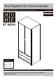
New Pagnell 2 Dr 2 Drw Wardrobe 601/9435 Assembly Instructions - Please keep for future reference 601/6524 601/8436 Dimensions Width - 76cm Depth - 54.5cm Height - 180.
Safety and Care Advice Important – Please read these instructions fully before starting assembly • Check you have all the components and tools listed on the following pages. • Remove all fittings from the plastic bags and separate them into their groups. • Keep children and animals away from the work area, small parts could choke if swallowed. • Make sure you have enough space to layout the parts before starting. • Do not use this item if any components are missing or damaged.
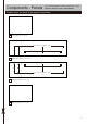
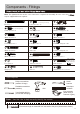
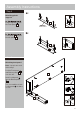
Components - Panels If you have damaged or missing components, call the Customer Helpline: Argos = 0345 6400800 Please check you have all the panels listed below 1 Top panel (76.2 x 54cm) Pilot holes for guidance only 2 Right side panel (179 x 52cm) Pilot holes for guidance only 3 Left side panel (179 x 52cm) 4 Middle panel (73 x 51.
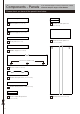
Components - Panels If you have damaged or missing components, call the Customer Helpline: Argos = 0345 6400800 Please check you have all the panels listed below 5 Bottom panel (73 x 11cm) 13 Drawer left side panel x 2 (34 x 11.5cm) 6 Bottom support (73 x 11cm) 7 Front panel (73 x 7cm) 8 14 Drawer bottom panel x 2 (70.7 x 33.6cm) Middle support (73 x 11cm) Pilot holes for guidance only 9 Door x 2 (138.2 x 36.1cm) 10 Drawer front panel x 2 (72.3 x 14.4cm) 11 Drawer back panel x 2 (69.8 x 11.
Components - Fittings Note: The quantities below are the correct amount to complete the assembly. In some cases mor may be supplied than are required.
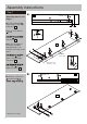
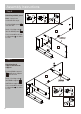
Assembly Instructions Step 1 a: Attaching runners and hinges a: Position Runners 2 Middle hole A B A in front edge of the Right side panel 2 . 1.7cm T Slide top of the Runner A back. T D E E C B Runners A on the Right side panel 2 . D Note: The front part of the runner should be approximately 1.7cm from the front edge of the panel. C 2 D A A C B Finished front edge D Door hinges C ‘back plates’ onto the Right side panel 2 .
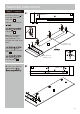
Assembly Instructions Step 1 - continued c: c: Position Runners A in front edge of the Left side panel 3 . Slide top of the Runners A . 3 Middle hole B A 1.7cm D D B C Runners A on the Left side panel 3 . T E D Note: The front part of C C the runner should be approximately 1.7cm from the front edge of the panel. D C B Pilot holes for guidance only 3 B D Door hinges C ‘back plates’ onto the Left side panel 3 .
Assembly Instructions Step 2 F F Fitting locking pins Screw Locking pins F into the Right side panel 2 and Left side panel 3 . F 2 F F Note: Insert locking pins as far as shown. Do not over tighten. F F F 3 F F F Step 3 G G Fitting dowels Insert Dowels G into the Bottom panel 5 , Bottom support 6 , Middle support 8 and Middle panel 4 . 5 6 I G G H I Stop H onto the Middle panel 4 .
Assembly Instructions Step 4 Attaching plastic supports a: a: K J K K J K supports J K Plastic onto the Front panel 7 . 7 J J back surface b: K Front panel 7 onto the Bottom panel 5 . b: K K K 7 K 5 Step 5 Attaching front panel Note: 2 people are need at this stage. Position Front panel 7 and Bottom panel 5 onto the unit. 2 L Insert Locking nuts L into the Bottom panel 5 . Use a screwdriver to turn Locking nuts L clockwise to lock.
Assembly Instructions Step 6 Attaching middle panel L Note: 2 people are needed at this stage. Position Middle panel 4 onto the unit. Insert 2 Locking nuts into the Middle panel L 4 2 . Use a screwdriver to turn Locking nuts L clockwise to lock. L back edge 4 L Step 7 L Attaching back support and bottom support Position Middle support 8 and Bottom support 6 onto the unit. 8 2 Insert 2 Locking nuts L into Middle support 8 back edge 6 and Bottom support .
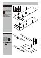
Assembly Instructions Step 8 Attaching left side panel L Position Left side panel 3 onto the unit. back edge 8 Insert 5 Locking nuts L into the Bottom panel 5 , Bottom support 6 , Middle support 8 and Middle panel 4 . 4 6 Use a screwdriver to turn Locking nuts L clockwise to lock. L 5 3 L L L L Step 9 Attaching top panel a: a: I Door Stop H onto the Top panel 1 . I I H H 1 Finished front edge Continued on next page.
Assembly Instructions Step 9 - continued b: Top panel unit. M 1 b: M onto the back edge M 1 M M 2 3 Step 10 Fixing back panel a: a: Apart the Ventilation holes covers X first. Attach Ventilation holes covers X onto Back panel 15 , comebine the covers. X X 15 Continued on next page.
Assembly Instructions Step 10 - continued b: Attach Back panel 15 onto the unit using Nails N . b: N back surface Important: The unit MUST be ‘square’ when back is attached. 15 2 3 6 Step 11 a: Drawer assembly a: Screw Locking pins F F F into 4 holes shown on back of the Drawer front panel 10 . 10 Note: Insert Locking pins F as far as shown. Do not over tighten. b: Fix Drawer left side panel 13 onto the Drawer front panel 10 . b: 13 10 Continued on next page.
Assembly Instructions Step 11 - continued c: Fix Drawer right side panel 12 onto the Drawer front panel 10 . c: O 12 Insert 2 Locking nuts O into the holes (they will only insert one way). 10 Use a screwdriver to turn Locking nuts O clockwise to lock. 13 O d: Insert 2 Locking nuts into the holes (they will only insert one way). O d: Use a screwdriver to turn Locking nuts O clockwise to lock. O O back surface 14 O O W 12 Place a small amount of Glue W into the grooves.
Assembly Instructions Step 12 Note: Wall plugs supplied are for solid wall only. K Fixing to wall V U Warning: In order to prevent overturning, this product must be used with the wall attachment device provided. U wall be used for your wall, seek professional advice if in doubt U U V Top panel K Wall straps(2 pcs) U onto the unit. Back panel With help, move this product into position. Warning: This product is heavy. Lift with care. remove this product .
Assembly Instructions Step 13 Inserting drawers and clothes rail a: With help, carefully stand wardrobe upright. Place Clothes rail Rail supports E . Q Q onto E Q Warning: The Wardrobe is heavy. Lift with care. a: Slide the drawers fully onto the runners so the runners butt up against the back of the drawer front. b: R R R R b: Fix through drawer sides into the runners using Screws R . R Step 14 D S Attaching hinges to doors S C Fix 3 Door hinges C onto Doors 9 using Screws D .
Assembly Instructions Step 15 Hanging doors a: With help, slot Door hinges C onto ‘hinge plates’. C b: Tighten screw shown to lock hinges in position. Repeat a and b for opposite door. 9 a: See ‘Hinge adjustment’ in step 15 if the doors need adjusting. C C 9 C b: C Step 16 Hinge adjustment a: To move doors up or a: D down: loosen screws shown and move doors to suit. Once doors are aligned, re-tighten Screws D . Door Continued on next page.
Assembly Instructions Step 16 - continued b: To move doors in or out: loosen screw shown and move doors to suit. b: Re-tighten screws. Door c: To move doors left or right: loosen screw shown and move doors to suit. c: Re-tighten screws. Note : Before use allow the glue to dry for 24 hours and make sure the unit is secure. Door Assembly is complete.
A Guide to - Wall Mounting & Fixings Important: When drilling into walls always Important note: If plastic wall plugs are supplied with your product: check that there are no hidden wires or pipes etc. Make sure that the screws and wall plugs being used are suitable for supporting your unit. Consult a qualified tradesperson if you are unsure. Hints: - these are only suitable for use in masonry walls. If you are in any doubt about the correct wall plugs for your wall, seek professional advice.