Kensington - 3 Drawer 2 Door Robe Assembly Instructions - Please keep for future reference 414/6946 4111335 Dimensions Width - 85.9cm Depth - 49.5cm Height - 198.8cm MADE IN BRITAIN Important - Please read these instructions fully before starting assembly If you need help or have damaged or missing parts, please visit www.argos-support.co.uk or email: Help@ClickSpares.co.uk (quoting your original order number) Alternatively, call the Spares Helpline on: 0370 112 1928.
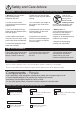
Safety and Care Advice Important - Please read these instructions fully before starting assembly • Warning: This unit weighs approximately 59kgs. Please lift with care. • Make sure you have enough space to layout the parts before starting. • Check you have all the components and tools listed on pages 2 and 3. • Do not stand or put weight on the product, this could cause damage. • Remove all fittings from the plastic bags and separate them into their groups.
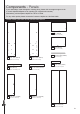
Components - Panels If you need help or have damaged or missing parts, please visit www.argos-support.co.uk or email: Help@ClickSpares.co.uk (quoting your original order number) Alternatively, call the Spares Helpline on: 0370 112 1928. For any other queries please contact the Customer Helpline on: 0345 640 2020 Please check you have all the panels listed below 8 Top (DF2409) (85.9 x 49.5cm) 9 Shelf (DF2413) (79.7 x 47.4cm) 10 Hanging Rail (FHR791) 6 Left Side (DF2410) (197.3 x 47.
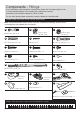
Components - Fittings If you need help or have damaged or missing parts, please visit www.argos-support.co.uk or email: Help@ClickSpares.co.uk (quoting your original order number) Alternatively, call the Spares Helpline on: 0370 112 1928. For any other queries please contact the Customer Helpline on: 0345 640 2020 Please check you have all the fittings listed below Note: The quantities below are the correct amount to complete the assembly. In some cases more fittings may be supplied than are required.
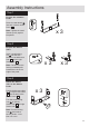
Assembly Instructions Step 1 A Prepare the 3 drawer fronts A A Screw 2 metal dowels A into each of the 3 drawer fronts 1 . 1 x3 Note: Tighten the metal dowels up fully against the panels. Step 2 Prepare the drawer sides C Insert a small locking nut C into the hole shown on the left drawer side 2 and the right drawer side 3 . C C 3 2 x3 Note: The arrow on the locking nut must point towards the hole in the edge of the panel.
Assembly Instructions Step 4 Fit the drawer base 5 Slide the drawer base 5 down the grooves in the drawer sides 2 and 3 and down into the groove in the drawer front 1 . 2 3 x3 1 Step 5 Fit the drawer back Fit the drawer back 4 between the drawer sides 2 and 3 . Make sure that the drawer base 5 fits into the groove in the drawer back 4 . F F 3 4 5 F F Hold the drawer back 4 in position and tap the knock-in pegs F through the holes in the drawer sides 2 and 3 .
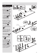
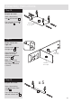
Assembly Instructions Step 8 P J Prepare the left side M P a: Place 3 runners M on the left side 6 as shown. Slide back the top of runner and use the 2nd hole from the front to fit the 1st screw J . Fit 3 hinge plates P onto the left side 6 , making sure that the slot is facing towards the finished front edge. Finished front edge P P J J a: 6 J M M M b: Slide the runners M back the other way and fit the 2nd screw J into the corresponding holes in the left side 6 .
Assembly Instructions Step 9 J Prepare the right side P M a: Place 3 runners M on the right side 7 as shown. Slide back the top of runner and use the 2nd hole from the front to fit the 1st screw J . P P a: 7 J J J Fit 3 hinge plates P onto the right side 7 , making sure that the slot is facing towards the finished front edge. M M M b: Slide the runners M back the other way and fit the 2nd screw J into the corresponding holes in the right side 7 .
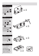
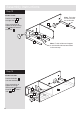
Assembly Instructions Step 10 Prepare the shelf B D D B B Insert 4 large locking nuts B into the shelf 9 . B 9 Tap 4 wooden dowels D into the shelf 9 . Finished front edge D D Step 11 A Fit the shelf to the right side B Push the shelf 9 onto the right side 7 . 7 Use a screwdriver to tighten the 2 large locking nuts B fitted to the shelf 9 . Finished front edge 9 Note: Turn the large locking nuts B as far as they will go - more than 1/2 a turn.
Assembly Instructions Step 13 Fit the 5 rails Note: The holes for this rail must be on this side Push the 5 rails 11 onto the right side 7 . 7 Use a screwdriver to tighten the large locking nut B fitted to each of the 5 rails 11 . 11 11 11 11 11 Note: Fit this rail last and support it until the left side has been fitted in the next step. Step 14 Fit the left side Push the left side 6 onto the assembly. Use a screwdriver to tighten the 2 large locking nuts B fitted to the shelf 9 and the 5 rails 11 .
Assembly Instructions Step 15 Prepare the top A A A Screw 4 metal dowels A into the top 8 . A 8 Step 16 Fit the top Note: To make it easier to fit the top and plinths, place polystyrene blocks from the packaging underneath the side panels to raise the assembly. Warning: The unit is heavy. Lift with care. Polystyrene block Polystyrene block 8 Push the top 8 onto the assembly. Polystyrene block Use a screwdriver to tighten the 4 large locking nuts B fitted to the sides 6 and 7 .
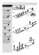
Assembly Instructions Step 18 a: Fit the back The measurement from top corner X to bottom corner X must be equal to the measurement from top corner Y to bottom corner Y a: Square up the unit by making sure that measurement x to x equals y to y. b: Place the back x b: y E 16 onto the unit. 16 Nail E around the outside edges of the back 16 . y Note: Nails should be spaced about 150mm apart.
Assembly Instructions Step 20 Finished top edge B Prepare a side plinth Insert a large locking nut B into 1 of the side plinths 13 . 13 D Tap a wooden dowel D into the side plinth 13 . Step 21 Prepare the other side plinth B D Finished top edge Insert a large locking nut B into the side plinth .13 . 13 Tap a wooden dowel D into the side plinth 13 . Step 22 A Prepare the front plinth Profiled top edge Screw 2 metal dowels A into the front plinth 12 .
Assembly Instructions Step 24 Fit the plinths Position the 3 plinths around the outside of the assembly, ensuring that the bottom edge of the plinths are flush with the bottom edge of the sides, as shown. 13 Secure the 2 side plinths 13 through the left end 6 and right end 7 using screws G . 7 G G G G 13 6 13 Carefully stand the unit up for the next step. Warning: The unit is heavy. Lift with care.
Assembly Instructions Step 26 Fit the hanging rail and shelf studs 10 Push the hanging rail 10 into the rail holders O fitted to the side panels. 10 O Push the 2 shelf studs S down into the holes in the shelf 9 to act as door buffers. S Step 27 S K K Prepare the 2 doors K Push fit 3 hinges Q into each of the 2 doors 14 and 15 . Secure each hinge with 2 screws K . Note: Before securing with the screws, make sure that the hinges are positioned at 90 degrees with the edge of the door.
Assembly Instructions Step 28 a: P Fit doors and handles Q A onto the front part of the hinge plate P . The recess at the bottom of screw B goes into the slot in the hinge plate. b: Keep the hinge B c: P Q Q Note: The easiest way to attach each door 14 and .15 is to fit the top hinge first, then align and fit the other hinges. a: Push the hinge b: P Q d: P P Q Q B Q FLAT against the hinge plate P as you slide it across as far as it will go. Tighten screw A.
Assembly Instructions Step 29 Adjust the doors if needed a: a: Before adjusting the doors, use a spirit level to check the base (or top) of the unit is level, front-to-back and side-to-side in the 3 positions shown. Use suitable packing pieces (not supplied) to make the unit level BEFORE making any adjustment to the hinges, as shown. b: A A b: Height adjustment. Loosen screws A on hinge plates and move door up or down as required. Retighten screw A. c: B c: Forward and Back adjustment.
Assembly Instructions Step 30 Strap T Washer Strap F Screw (not supplied) U N IT Washer O Wall fixing (not supplied) Screw T P To prevent possible overbalancing we recommend that this unit is secured to a suitable wall by fitting of the overbalance protector kit .T to the unit, or an alternative fixing method of your choice. L L WA TO Fit the overbalance protector T Wall fixings are not supplied as they will need to suit the wall type.
ALR3177
Kensington - 3 Drawer Bedside Assembly Instructions - Please keep for future reference 423/7824 426/5487 Dimensions Width - 48.5cm Depth - 39.4cm Height - 76.1cm MADE IN BRITAIN Important - Please read these instructions fully before starting assembly If you need help or have damaged or missing parts, please visit www.argos-support.co.uk or email: Help@ClickSpares.co.uk (quoting your original order number) Alternatively, call the Spares Helpline on: 0370 112 1928.
Safety and Care Advice Important - Please read these instructions fully before starting assembly • Warning: This unit weighs approximately 20kgs. Please lift with care. • Make sure you have enough space to layout the parts before starting. • Check you have all the components and tools listed on pages 1, 2 and 3. • Do not stand or put weight on the product, this could cause damage. • Remove all fittings from the plastic bags and separate them into their groups.
Components - Panels If you need help or have damaged or missing parts, please visit www.argos-support.co.uk or email: Help@ClickSpares.co.uk (quoting your original order number) Alternatively, call the Spares Helpline on: 0370 112 1928. For any other queries please contact the Customer Helpline on: 0345 640 2020 Please check you have all the panels listed below 1 Left Side (DF2404) 2 Right Side (DF2405) 3 Top (DF2380) 4 Rail (DF2383) 5 Front Plinth (DF2385) 6 Side Plinth (DF2386) (37.4 x 9.
Components - Fittings If you need help or have damaged or missing parts, please visit www.argos-support.co.uk or email: Help@ClickSpares.co.uk (quoting your original order number) Alternatively, call the Spares Helpline on: 0370 112 1928. For any other queries please contact the Customer Helpline on: 0345 640 2020 Please check you have all the fittings listed below Note: The quantities below are the correct amount to complete the assembly. In some cases more fittings may be supplied than are required.
Assembly Instructions If you have damaged or missing components, call the Customer Helpline: 03456 400800 quoting the reference numbers below Step 1 A Prepare the 3 drawer fronts Screw 2 metal dowels A into each of the drawer fronts 7 . A A x3 7 Note: Tighten the metal dowels up fully against the panels. Step 2 Prepare the drawer sides C Insert a small locking nut C into the hole shown on the left drawer side 8 and the right drawer side 9 .
Assembly Instructions Step 4 Fit the drawer base Slide the drawer base 11 down the grooves in the drawer sides 8 and 9 and down into the groove in the drawer front 7 . 11 x3 9 8 7 Step 5 Fit the drawer back Fit the drawer back 10 between the drawer sides 8 and 9 . Make sure that the drawer base 11 fits into the groove in the drawer back 10 . Hold the drawer back 10 in position and tap the knock-in pegs F through the holes in the drawer sides 8 and 9 .
Assembly Instructions Step 8 J Prepare the left side M a: Place 3 runners M on the left side 1 as shown. Slide back the top of runner and use the 2nd hole from the front to fit the 1st screw J . b: Slide the runner M back the other way and fit the 2nd screw J into the corresponding hole in the left side 1 . Finished front edge J J J M 1 M a: M c: Screw 5 metal dowels A into the left side 1 . Finished front edge Insert 2 large locking nuts B into the left side .1 .
Assembly Instructions Step 9 J Prepare the right side M a: Place 3 runners M on the right side 2 as shown. Slide back the top of runner and use the 2nd hole from the front to fit the 1st screw J . b: Slide the runner M back the other way and fit the 2nd screw J into the corresponding hole in the right side 2 . J J 2 a: J M M M Finished front edge c: Screw 5 metal dowels A into the right side 2 . J Insert 2 large locking nuts B into the right side 2 .
Assembly Instructions Step 10 Prepare the 5 rails B D B Insert 2 large locking nuts B into each of the 5 rails 4 . x5 4 Tap 2 wooden dowels D into each of the 5 rails 4 . Step 11 Fit 3 of the rails to the right side D A B Push 3 rails 4 onto the right side 2 . 2 Use a screwdriver to tighten the large locking nut B fitted to each of the rails 4 . 4 4 4 Note: Turn the large locking nuts B as far as they will go - more than 1/2 a turn.
Assembly Instructions Step 13 Fit the left side Push the left side 1 onto the rails 4 . 4 4 4 Use a screwdriver to tighten the large locking nut B fitted to each of the rails 4 . 1 4 4 A Step 14 A A Prepare the top A Screw 4 metal dowels A into the top 3 . 3 Profiled front edge Step 15 Fit the top Note: To make it easier to fit the top and plinths, place polystyrene blocks from the packaging underneath the side panels to raise the assembly. 3 2 1 Push the top 3 onto the assembly.
Assembly Instructions Step 16 a: Fit the back The measurement from top corner X to bottom corner X must be equal to the measurement from top corner Y to bottom corner Y a: Square up the unit by making sure that measurement x to x equals y to y. b: Place the back b: x E 12 y onto the unit. 12 y Nail E around the outside edges of the back 12 . x Note: Nails should be spaced about 150mm apart.
Assembly Instructions Step 18 Finished top edge B Prepare a side plinth Insert a large locking nut B into 1 of the side plinths 6 . 6 D Tap a wooden dowel D into the side plinth 6 . Step 19 Prepare the other side plinth B D Finished top edge Insert a large locking nut B into the side plinth .6 . 6 Tap a wooden dowel D into the side plinth 6 . Step 20 A Prepare the front plinth A Screw 2 metal dowels A into the front plinth 5 .
Assembly Instructions Step 22 Fit the plinths Position the 3 plinths onto the assembly ensuring that the bottom edge of the plinths are flush with the bottom edge of the sides, as shown. Secure the 2 side plinths . 6 through the left end . 1. and right end 2 using screws G . 6 1 G G G 2 6 G 6 Carefully stand the unit up for the next step.
Assembly Instructions Step 24 O Strap O Strap Washer IT Wall fixing (not supplied) Attach the strap to the unit N To prevent possible overbalancing we recommend that this unit is secured to a suitable wall by fitting of the overbalance protector kit .O to the unit, or an alternative fixing method of your choice. Attach the strap to the wall U Fit the overbalance protector kit Example Screw (not supplied) Wall fixings are not supplied as they will need to suit the wall type.
ALR3179
Kensington - 5 Drawer Chest Assembly Instructions - Please keep for future reference 397/6337 392/6648 Dimensions Width - 48.5cm Depth - 39.4cm Height - 118.7cm MADE IN BRITAIN Important - Please read these instructions fully before starting assembly If you need help or have damaged or missing parts, please visit www.argos-support.co.uk or email: Help@ClickSpares.co.uk (quoting your original order number) Alternatively, call the Spares Helpline on: 0370 112 1928.
Safety and Care Advice Important - Please read these instructions fully before starting assembly • Warning: This unit weighs approximately 37kgs. Please lift with care. • Make sure you have enough space to layout the parts before starting. • Check you have all the components and tools listed on pages 2 and 3. • Do not stand or put weight on the product, this could cause damage. • Remove all fittings from the plastic bags and separate them into their groups.
Components - Panels If you need help or have damaged or missing parts, please visit www.argos-support.co.uk or email: Help@ClickSpares.co.uk (quoting your original order number) Alternatively, call the Spares Helpline on: 0370 112 1928. For any other queries please contact the Customer Helpline on: 0345 640 2020 Please check you have all the panels listed below 3 Top (DF2403) (70.8 x 39.4cm) 1 Left Side (DF3754) (117.2 x 37.4cm) 2 Right Side (DF3755) (117.2 x 37.4cm) 4 Rail (DF2406) (64.6 x 9.
Components - Fittings If you need help or have damaged or missing parts, please visit www.argos-support.co.uk or email: Help@ClickSpares.co.uk (quoting your original order number) Alternatively, call the Spares Helpline on: 0370 112 1928. For any other queries please contact the Customer Helpline on: 0345 640 2020 Please check you have all the fittings listed below Note: The quantities below are the correct amount to complete the assembly. In some cases more fittings may be supplied than are required.
Assembly Instructions Step 1 A Prepare the 5 drawer fronts Screw 2 metal dowels A into each of the drawer fronts 7 . A A x5 7 Note: Tighten the metal dowels up fully against the panels. Step 2 Prepare the drawer sides C Insert a small locking nut C into the hole shown on the left drawer side 8 and the right drawer side 9 . C C Note: The arrow on the locking nut must point towards the hole in the edge of the panel.
Assembly Instructions Step 4 Fit the drawer base x5 11 Slide the drawer base 11 down the grooves in the drawer sides 8 and 9 and down into the groove in the drawer front 7 . 9 8 7 Step 5 Fit the drawer back Fit the drawer back 10 between the drawer sides 8 and 9 . Make sure that the drawer base 11 fits into the groove in the drawer back 10 . Hold the drawer back 10 in position and tap the knock-in pegs F through the holes in the drawer sides 8 and 9 .
Assembly Instructions Step 8 J Prepare the left side M a: Place 5 runners M on the left side 1 as shown. Slide back the top of runner and use the 2nd hole from the front to fit the 1st screw J . J Finished front edge J M J M J b: Slide the runner M back the other way and fit the 2nd screw J into the corresponding hole in the left side 1 . J M 1 M a: M c: Screw 8 metal dowels A into the left side 1 . Insert 2 large locking nuts B into the left side .1 .
Assembly Instructions Step 9 J Prepare the right side M a: Place 5 runners M on the right side 2 as shown. Slide back the top of runner and use the 2nd hole from the front to fit the 1st screw J . b: Slide the runner M back the other way and fit the 2nd screw J into the corresponding hole in the right side 2 . J J J J J a: 2 M M M M Finished front edge M c: Screw 8 metal dowels A into the right side 2 . J J J Insert 2 large locking nuts B into the right side 2 .
Assembly Instructions Step 10 Prepare the 8 rails B D B Insert 2 large locking nuts B into each of the 8 rails 4 . x8 4 Tap 2 wooden dowels D into each of the 8 rails 4 . Step 11 Fit 5 of the rails to the right side D A B Push 5 rails 4 onto the right side 2 . 2 Use a screwdriver to tighten the large locking nut B fitted to each of the rails 4 . 4 4 4 4 Note: Turn the large locking nuts B as far as they will go - more than 1/2 a turn.
Assembly Instructions Step 13 Fit the left side Push the left side 1 onto the rails 4 . 4 Use a screwdriver to tighten the large locking nut B fitted to each of the rails 4 . 4 4 4 4 4 4 1 4 4 A Step 14 A Prepare the top Screw 4 metal dowels A into the top 3 .
Assembly Instructions Step 15 Polystyrene block Fit the top Note: To make it easier to fit the top and plinths, place polystyrene blocks from the packaging underneath the side panels to raise the assembly. 3 2 Push the top 3 onto the assembly. 1 Polystyrene block Use a screwdriver to tighten the 2 large locking nuts B fitted to each of the sides 1 and .2 .
Assembly Instructions Step 17 Fit the 4 plastic nails Tap 2 plastic nails L into the bottom edge of each of the sides 1 and .2 . L 2 L L 1 L Step 18 B Prepare a side plinth Insert a large locking nut B into 1 of the side plinths 6 . Finished top edge 6 D Tap a wooden dowel D into the side plinth 6 . Step 19 Prepare the other side plinth Insert a large locking nut B into the side plinth .6 . Tap a wooden dowel D into the side plinth 6 .
Assembly Instructions A Step 20 Prepare the front plinth A Profiled top edge Screw 2 metal dowels A into the front plinth 5 . 5 Step 21 Finished top edge Fit the plinths together 6 Push the 2 side plinths 6 onto the front plinth 5 . Finished top edge Profiled top edge Use a screwdriver to tighten the large locking nuts B fitted to the side plinths 6 .
Assembly Instructions Step 23 Fix the front plinth Secure the front plinth 5 through the rail 4 using screw G . Carefully stand the unit up for the next step. G Warning: The unit is heavy. Lift with care. 4 5 Step 24 Fit the drawers Starting with the bottom drawer, slide both the runners M forward and locate the drawer sides 8 and 9 between them, lining up the holes in the drawer wrap with the 2nd 'threaded' holes in the runners M .
Assembly Instructions Step 24 O Strap O Screw Washer Strap Washer IT Wall fixing (not supplied) Attach the strap to the unit N To prevent possible overbalancing we recommend that this unit is secured to a suitable wall by fitting of the overbalance protector kit .O to the unit, or an alternative fixing method of your choice. Attach the strap to the wall U Fit the overbalance protector kit Example Screw (not supplied) Wall fixings are not supplied as they will need to suit the wall type.
ALR3180