
Assembly Instructions

Assembly Instructions
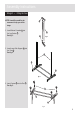
Stage 3 –
Fitting the Hanger
1.
Insert Hanger
A
into the Lock
.
See fig. 6.
NOTE: It would be useful to ask
someone to help you at this
stage.
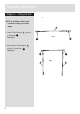
2. Insert Locks into the Lower
Side Support B .
See fig. 7.
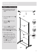
3.
Insert Locks
into the bottom
of Upper Side Support .
D
4.
Set the height of the unit:
Using the holes on Upper Side
Support D . Ensuring the Locks
are loosened See fig.8., slide
the Upper Side Support D to the
desired height and tighten the
Locks to fix in position.
See fig. 9 . & fig. 10.
Adjustment Range:99.5 ~ 167 cm.
fig. 7
B
D
fig. 6
A
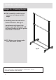
fig. 9
Locked
fig. 8
Unlocked
fig. 10
NOTES : Align all the holes of the
componets , before locking.
B
D
&
B
B
B
B
B
B
B
B
B
B
6