SAN DIEGO - TV Unit Assembly Instructions - Please keep for future reference 389/6620 Dimensions Width - 125cm Depth - 40cm Height - 50cm Important – Please read these instructions fully before starting assembly If you need help or have damaged or missing parts, call the Customer Helpline: 03456 400 800 Issue 1 - 15/04/15
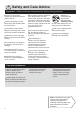
Safety and Care Advice Important – Please read these instructions fully before starting assembly Check you have all the components and tools listed on pages 2 and 3. Remove all fittings from the plastic bags and separate them into their groups. Keep children and animals away from the work area, small parts could choke if swallowed. Make sure you have enough space to layout the parts before starting. Do not stand or put weight on the product, this could cause damage.
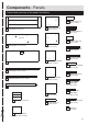
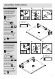
Components - Panels Please check you have all the panels listed below top 15 Drawer front x 2 (26.2 x 12.6cm) 1 Top panel (125 x 40cm) 9 Right side panel (47.2 x 37cm) 16 Drawer sides x 4 (34 x 12cm) underside top 17 Drawer back x 2 (23.8 x 12cm) 2 Base panel (116 x 35.4cm) 10 Left side panel (47.2 x 37cm) 18 Right front frame (47.2 x 6.5cm) 19 Left front frame (47.2 x 6.5cm) 3 Back panel (117.8 x 38.6cm) 11 Middle right panel (35.8 x 35.4cm) 20 Middle right frame (35.3 x 6.
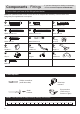
Components - Fittings If you have damaged or missing components, call the Customer Helpline: 03456 400 800 Please check you have all the fittings listed below Note: The quantities below are the correct amount to complete the assembly. In some cases more fittings may be supplied than are required.
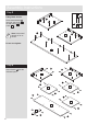
Assembly Instructions Step 1 a: Fixing right front frame to the right side panel (Two people required for an easier assembly). a: Insert right side panel 9 into right front frame 18 through joints. b: 18 D 9 No! Note: Before fixing blocks 25 into place it is important to ensure that the slot and groove of parts 9 and 18 are fully pushed together and lined up correctly at the top and bottom. b: Place blocks c: D 25 Yes! Attention: correct position of panel.
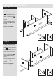
Assembly Instructions Step 3 Fitting Metal dowels. H H Screw metal dowels H into right side panel 9 , left side panel 10 and top panel 1 . 10 H Note: Insert metal dowels as far as shown. H 9 H Do not over tighten. H 1 H Step 4 A A Insert dowels A into the indicated parts.
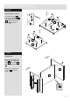
Assembly Instructions Step 5 Fixing drawer runners. E E Fit drawer runners 24 to the right side panel 9 and middle right panel 11 then fix them using screws E as shown. E 24 24 24 9 E E 24 24 11 Step 6 Fixing shelf. With help, fit middle right panel 11 and middle left panel 12 to the shelf 13 then fix it using screws D . D Make sure round edge on shelf 13 must face down.
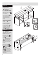
Assembly Instructions Step 7 12 Fixing middle panels. With help, fit middle panels to the base panel 2 then fix them using screws E . 11 E 2 Make sure round edge on base panel 2 must face down. E E E 2 Step 8 Assembling parts. 21 Put parts 5 , 6 , 20 , 21 , 22 and 23 together as shown in the diagram. 5 22 20 6 23 Step 9 Insert the assembled frame into the holes on left side panel 10 .
Assembly Instructions Step 10 Fixing base panel. With help, fit base panel 2 to the left side panel. 10 Insert 2 locking nuts I into base panel where shown. I Use a screwdriver to turn locking nuts I clockwise to lock. I 2 Do not over tighten. I I Step 11 Fixing right side panel. With help, place right side panel 9 properly ensuring dowels and front frames are all fit into their holes at the same time. Insert 2 locking nuts I into base panel where shown.
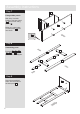
Assembly Instructions Step 12 Fixing top panel. Important: With help, carefully stand the product upright. 1 I I With help, fit top panel 1 to the cabinet. Insert 8 locking nuts I into side panels and middle panels where shown. O I I I Use a screwdriver to turn locking nuts I clockwise to lock. I O Do not over tighten. Fix metal brackets O in the middle panels and middle frames using screws B as shown. B B I Step 13 Important: With help, carefully lay down the product.
Assembly Instructions Step 14 Fix block 25 to the front plinth and bottom front frame using screws D . 25 D D Step 15 Fitting hinges to door. B Attach hinges L in the pre marked holes on door 7 using screws B as shown. J Attach handle J to the door using bolt G as shown.
Assembly Instructions Step 16 Fixing door. Important: With help, carefully stand the product upright. B With help centralise the door in the opening of the cabinet then fix the hinges using screws B as shown. 7 Note: Hinges allow some adjustment after doors are fixed. Loosen screws and move doors to suit. Re-tighten screws. Note: Step 17 Fitting door lock. a: Screw clip M in place using screws B . Ensure that the 2 small wheels are flush with the edge of the base as shown in the diagram.
Assembly Instructions Step 18 Drawer assembly. a: 16 C a: Attach drawer sides 16 15 b: to the drawer front using screws C . 17 16 15 8 b: Slide drawer bottom 8 into slots on drawer sides and position drawer back 17 in place. C c: Holding the drawer c: back 17 , press the drawer sides and fix them using screws C . d: Using bolts attach drawer handle K to drawer front. 2x C d: C F F Repeat step 18 for the other drawer. K Step 19 Insert drawers into unit.
Assembly Instructions Step 20 Fixing back panel. Important: Cabinet MUST be ‘square’ when back panel are attached. Attach back panel 3 using nails P . P P 3 P P Assembly is complete.