TECHNICAL DATA & SERVICE MANUAL - AUR101CL COOLING ONLY VERSION (R407C) - AUR131CL - AUR101HL HEAT PUMP VERSION (R407C) ROOM AIR CONDITIONER WITH REMOTE CONDENSER 0.8180.237.
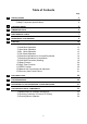
Table of Contents Page A SPECIFICATIONS 1) Unit specifications 2) Major Component specifications 3 3 4 B OPERATING RANGE 5 C DIMENSIONAL DATA 6 D PERFORMANCE CHARTS 7 E REFRIGERANT FLOW DIAGRAM 9 F FUNCTION 1) Cool Mode Operation 2) Heat Mode Operation 3) Auto Mode Operation 4) Dry Mode Operation 5) Fan Mode Operation 6) Protection Operations in Cool and Dry Modes 7) Protection Operations in Heat Mode 8) Cold Draft Prevention (Heating) 9) Sleep Function 10) Daily Timer Function 11) IFEEL F
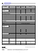
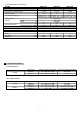
A SPECIFICATIONS 1) UNIT SPECIFICATIONS UNIT MODEL AUR101CL AUR131CL Power source AUR101HL 220 - 240 V ~ 50 Hz PERFORMANCES COOLING BTU / h Capacity W Air circulation (high/med/low) Moisture removal (high speed) 9045 2650 COOLING HEATING 12525 9560 10720 3670 2800 3140 m3 / h 370/340/270 450/400/340 370/340/270 l /h 1.2 1.5 1.2 ELECTRICAL RATINGS 220 ÷ 240 Voltage rating V Available voltage range V Running ampere A 4.4 6.2 4.2 4.
2) MAJOR COMPONENT SPECIFICATIONS a) INDOOR UNIT MODEL CONTROLLER P.C.B.
b) OUTDOOR UNIT (LITTLE BAG) MODEL FAN & FAN MOTOR Number / Diameter No of pole / rpm (220 V, high) Nominal output Coil resistance (at 25 °C) Safety device Open Close Setting Run capacitor (C2) THERMISTOR (COIL SENSOR) TH3 Resistance (at 25 °C) HEAT EXCHANGE COIL Coil Rows Fin pitch Face area B AUR101CL AUR131CL AUR101HL Propeller Propeller Propeller mm 1 / ø 320 1 / ø 380 1 / ø 380 4 / 1205 6 / 860 6 / 860 W 58 70 70 BLU-BRN: 249 ÷ 287 BLU-BRN: 218 ÷ 251 BLU-BRN: 218 ÷ 251 Ω BLU-BLK: 270 ÷ 311 BLU-BLK:
C DIMENSIONAL DATA Indoor unit 790 835 580 245 245 435 (* 490) 425 Outdoor unit 440 440 (* 490) 230230 (* 250) DIMENSIONS: mm * HEAT PUMP MODEL AND AUR131CL 6
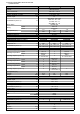
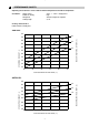
PERFORMANCE CHARTS Operating characteristics versus outdoor ambient temperature and indoor temperature. Conditions: Power source Indoor air velocity Refrigerant Tubing length 230 V - 1 - 50Hz - Single phase High Amount charged at shipment 2,5 m Cooling characteristics Indoor relative humidity 46% AUR101CL 5.2 32 4.8 27 4.6 OPERATING CURRENT - A 4.4 19 4.2 4.0 3.8 3.6 INDOOR INLET AIR D.B. TEMP. (°C) 5.0 3.4 3.2 20 25 30 35 40 45 OUTDOOR INLET AIR D.B. TEMP. (°C) AUR131CL 32 6.5 27 6.
Operating characteristics versus outdoor ambient temperature and indoor temperature. Conditions: Power source Indoor air velocity Refrigerant Tubing length 230 V - 1 - 50Hz High Amount charged at shipment 2,5 m HEAT PUMP MODELS Cooling characteristics Indoor relative humidity 46% … 5.0 … 5.2 32 27 4.6 4.4 19 4.0 … OPERATING CURRENT - A 4.2 3.8 3.6 3.4 INDOOR INLET AIR D.B. TEMP. (°C) 4.8 3.2 3.0 20 25 30 35 40 45 OUTDOOR INLET AIR D.B. TEMP.
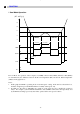
REFRIGERANT FLOW DIAGRAM COOLING MODELS Indoor unit Heat exchanger Heat exchanger Mechanical filter Outdoor unit CAPILLARY TUBE Compressor Accumulator QUICK CONNECTOR REFRIGERANT FLOW DIAGRAM HEAT PUMP MODELS Compressor Indoor unit Accumulator Muffler 4-way valve Heat exchanger Outdoor unit Heat exchanger E Capillary tube Capillary tube ( ) Quick connector Stainer Drier Check valve Cooling cycle Heating cycle 9
F FUNCTION 1 Cool Mode Operation (RT - SPT) [ oc] +3 +2 +1 0 -1 over 3 min over 5 min ON COMP OFF ON OFAN OFF over 30 sec H IFAN M L ON RV OFF In Cool Mode, the operation of the Compressor (COMP), Outdoor Fan (OFAN) and Indoor Fan (IFAN) are determined by the difference between the Room Temperature (RT) and the Set Point Temperature (SPT) as in the graph above. Notes: 1. In this graph, the IFAN is operating in the “Auto Fan Speed” setting.
2 Heat Mode Operation (RT - SPT) [oc] +1 0 -1 -2 -3 ON COMP OFF 30 sec H M IFAN L OFF Note 1 Note 2 ON RV OFF The Heat Mode operation is similar to the Cool Mode operation. The COMP, OFAN and IFAN are mainly controlled by the value of (RT – SPT). In the graph above, the IFAN is operating in Auto Fan speed mode. Therefore, the IFAN speed changes automatically according to the (RT - SPT). Note 1: The 30s IFAN operation is for purging the heat from the in-coil after COMP has stopped.
3 Auto (Cool/Heat) Mode Operation (RT - SPT) [oc] +2 +1 0 -1 -2 ON COMP & OFAN OFF ON RV OFF Auto Heat Mode Auto Cool Mode Auto Heat Mode In Auto Mode, the unit switches between the Auto Cooling Mode and Auto Heating Mode automatically to maintain the room temperature (RT) at the set point temperature (SPT).
4 Dry Mode Operation (RT - SPT) [oc] +2 +1 0 10 20 40 30 50 Time [min] -1 -2 DRY-ON DRY DRY-OFF LOW IFAN OFF 5 minutes COMP ON time ON COMP & OFAN OFF Max 15 minutes 3.5 min Max 15 minutes (Note 1) 6 min (Note 2) In Dry Mode, the unit operates in a mild cool mode to lower the humidity of the room. In order to maintain a high efficiency in the drying operation without over lowering the room temperature excessively, the Dry Mode is different from the Cool Mode in two ways. 1.
6 Protection Operations in Cool and Dry Modes 1. Indoor Coil Defrost Protection The in-coil defrost protection can prevent the ice formation at the in-coil when the ambient temperature is low.
2. Outdoor Coil High Pressure Protection The out-coil high pressure protection prevent the build up of high pressure at the out-coil during cooling operation. OCT [oc] 64 61 55 52 ANY COMP OFF COMP is forced OFF OFAN follow operation of COMP ANY OFAN OFAN is forced ON (Note 1) ON ANY IFAN L IFAN is forced LOW ON OPER LED Note 1: BLINK In some applications, the outdoor fan and the compressor are controlled together by the COMP relay output from the controller.
7 Protection Operations in Heat Mode 7-1 Outdoor Coil Deice Protection The deice process is controlled by an Ice Detection Algorithm (IDA). The IDA is an unique control algorithm incorporated to maintain optimal utilization of the heat pump capacity, especially in below-zero outdoor temperature condition. The out-coil deicing will be activated not only by static temperature detection as normally done, but also while ice forming is detected on the out-coil.
1st COMP start, OR deice complete Yes No Reset TLD cnt to 0 DTF = 0 IFAN/OFAN speed change Yes No Reset SCT cnt to 0 DTF = 0 TLD > TST AND SCT > SCD Yes No DDT = OCT - TempD DTF = 1 DDT and DTF information to main algorithm Explanation: The “Ice Forming Detection” will be done by two algorithms – 1. In Dynamic Temp Detection, the ice formation will be detected by (i) Compare the OCT with a Deicing Dynamic Temperature Threshold, and (ii) Detect the drop in ICT which accompany the ice formation. 2.
7-2 Indoor Coil High Pressure Protection in Heat Mode The in-coil high pressure protection prevent the build up of high pressure at the in-coil during heating operation. ICT [oc] 64 A B ANY COMP OFF COMP is forced OFF ANY OFAN OFF Note: The operation temperatures shown as A and B in the chart differ by models.
8 Cold Draft Prevention (Heating) • This function controls indoor fan speed so a strong draft of cold air will not blow out before the indoor heat exchange coil have sufficiently warmed up. • When 10 minutes has elapsed, the fan speed is automatically switched to set speed regardless of indoor heat exchange coil temperature. Indoor heat exchange coil temp. (°C) Max.10 minutes Tc Indoor Fan OFF Set Speed NOTE • The operation temperature shown as Tc in the chart differ by models.
9 Sleep Function Room temperature is automatically controlled to compensate for body temperature variations while sleeping. This mode of operation is designed for maximal comfort in both COOL and HEAT modes.
12 Manual Unit Control and LED indicators The push button switch and the LED indicators on the display panel let the user to control the unit operation without a remote controller. Their operations are provided below. LED indicators: STAND BY INDICATOR OPERATION INDICATOR TIMER INDICATOR 1. Lights up when the Air Conditioner is connected to power and ready to receive the R/C commands 2. Blinks continuously in case of any thermistor failure. 1. Lights up in operation mode (Note: OFF in standby mode). 2.
ELECTRIC WIRING - COOLING ONLY VERSION • SCHEMA ELETTRICO - VERSIONE SOLO RAFFREDDAMENTO • SCHÉMA ÉLECTRIQUE VERSION FROID SEUL • SCHALTPLAN - AUSFÜHRUNG: NUR KÜLUNG • ESQUEMA ELECTRICO SCHALTPLAN - MODELOS QUE SOLO EINFRIAN • HLEKTRIKO DIAGRAMMA - EKDOSH MONO YUXH AUR101CL AUR131CL 22
ELECTRIC WIRING - HEAT PUMP VERSION • SCHEMA ELETTRICO - VERSIONE POMPA DI CALORE • SCHÉMA ÉLECTRIQUE - VERSION POMPE À CHALEUR • SCHALTPLAN - WÄRMEPUMPE-AUSFÜHRUNG • ESQUEMA ELECTRICO SCHALTPLAN - MODELOS BOMBA DE CALOR • HLEKTRIKO DIAGRAMMA - EKDOSH ME QERMOANTLIA 23
TROUBLESHOOTING H CHECK BEFORE AND AFTER «TROUBLESHOOTING» (A) Check power supply wiring. ● WARNING: If the following troubleshooting must be done with power being supplied, be careful about any uninsulated live part that can cause ELECTRIC SHOCK. (B) Check power supply. ● ● Check that voltage is in specified range (± 10% of the rating).
C Water - level alarm (condensate) is blinking Malfunctioning of the condensate drainage system to the outdoor unit NOTE - In case of emergency the air conditioner can work by draining the condensate from the back little pipe into a rather short container, extract the little pipe and remove the cap.
E SOME PART OF AIR CONDITIONER DOES NOT OPERATE 1) ONLY INDOOR FAN DOES NOT RUN Check fan rotation. Turn fan gently once or twice by hand. Check fan motor capacitor. Fan cannot be turned DEFECTIVE Check fan casing for foreign matter on inside. Remove foreign matter or repair. Fan motor burnout or foreing matter in bearing. Repair or replace. Replace. OK Measure resistance of fan motor winding. DEFECTIVE Replace fan motor. 2) ONLY OUTDOOR FAN DOES NOT RUN Check fan rotation.
F AIR CONDITIONER OPERATES, BUT ABNORMALITIES ARE OBSERVED (HEAT PUMP MODEL) 1) Operation does not switch from heat to cool (or cool to heat) Remote control unit may be defective. Receiver Ass’y may be defective. Measure resistance of solenoid coil winding (20 S - 4-way valve) (2) Check “PUSH BUTTON” in indoor unit on monitor panel • • Push the button switch under the Push the button switch under the indoor unit pannel. indoor unit pannel.
(4) Check fuse on PCB Ass’y in indoor unit. Check fuse on PCB Ass’y in indoor unit for continuity. If fuse blows, there is a possibility of short circuit. Measure resistance of indoor fan motor winding (FMI). OK PCB Ass’y in indoor unit is defective. (5) Check setting temperature.
G POOR COOLING OR POOR HEATING Check position of remote control unit. Cool or warm air from air conditioner reaches position directly. Change position of remote control unit. NO Are wide and narrow tubes between indoor unit and outdoor unit insulated? Insultate wide and narrow tubes and then tape together. SI Measure temperatures of suction and discharge air of air conditioner. Possibility of gas shortage? Charge refrigerant gas.
I IF A SENSOR IS DEFECTIVE ICT (indoor coil sensor) OCT (outdoor coil sensor) RAT (room ambient temperature) are defective. • Stand by lamp on front side of indoor unit is blinking. (*) • YES Thermistor ICT and OCT and RAT are defective YES • Replace thermistor. NOTE Allarm signal (*) Stanby lamp on the front side of the indoor unit will blink when the thermistor is defective. At the same time the outdoor unit will stop. Indoor operate only for ventilation.
I PROCEDURE FOR THE REFRIGERANT CHARGE RESTORING TOTAL REFRIGERANT CHARGE R407C AUR101CL AUR131CL AUR101HL STANDARD UNIT 910 g 1220 g 1030 g UNIT WITH EXTENSION KIT OF 2 m 960 g 1270 g 1090 g UNIT WITH EXTENSION KIT OF 4 m 1010 g 1320 g 1150 g NOTE: The extension kits are supplied precharged. In order to ensure quick and safe connection to the vacuum pump, use the connection device which can be bought near Argo Service Dept.
Before starting the bleeding of the system, it is advisable to oil the quick connections with antifreezing oil (HAB OIL), and then connect and disconnect once the system, in order ensure that seals of the piston. Indoor unit bleeding Joint the service connection to the low pressure pipe of the vacuum pump, according to above instructions, the screw it to the female aeroquip connection of the indoor/outdoor connection pipe. Make vacuum inside the indoor unit (10 mm Hg. abs.).
L CHECKING ELECTRICAL COMPONENTS 1) Measurement of Insulation Resistance EATHER LINE ● The insulation is in good condition if the resistance exceeds 1MOhm. CLIP PROBE INSULATION TESTER a) Power Supply Wires Clamp the earthed wire of the power supply wires with the lead clip of the insulation resistance tester and measure the resistance by placing a probe on either of the power wires (Fig. 1). Then measure the resistance between the earthed wire and the other power wires (Fig. 1). Fig.
2) Checking Continuity of Fuse on PCB Ass’y ● Remove PCB Ass’y from electrical component box. (Fig. 5). ● FUSE Then pull out the fuse from PCB Ass’y. PCB ASS’Y Fig. 5 ● Check continuity of fuse by the multimeter (Fig. 6). FUSE Fig. 6 3) Checking Motor Capacitor ● Remove the lead wires from the capacitor terminals, and then place a probe on the capacitor terminals as shown in Fig. 7.
Tel. +39 0331 755111 - Fax +39 0331 776240 www.argoclima.