TECHNICAL DATA & SERVICE MANUAL MAGICO 9.2 AMG26MIR 0.8180.469.
Page 3 3 4 1. SPECIFICATIONS 1-1 Unit Specifications 1-2 Major Component Specifications 6 6 2. DIMENSIONAL DATA 2-1 Unit Dimensions 7 7 3. ELECTRICAL DATA 3-1 Electric Wiring Diagram 8 8 4. REFRIGERANT FLOW DATA 4-1 Refrigerant Flow Diagram 5.
1.
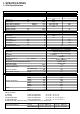
1-2 Major Component Specifications Controller PCB Controls Control circuit fuse (CE) Thermistor (coil sensor) Resistance (TH1) 25 °C NTC 10 °C ± 5% Thermistor (room sensor) Resistance (TH2) 25 °C NTC 10 °C ± 5% Fan & Fan Motor Type Q'ty ……. Dia. and lenght No. Of poles Rpm Power input (230 V) (FM) M01974 Centrifugal blower 1….
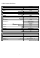
Safety devices Type Operating temperature Operating amperes (25 °C) (OLR) open close open with Run capacitor (compressor) °C °C (C3) µF VAC Condensate pump Model Nominal input (230 V) Winding resistance (PC) Pump relay Contact rating Coil supply Coil resistance (20 °C) (RP) W Ω Heat exchanger coil Coils Rows Fin pitch Face area Heat exchanger coil Coils Rows Fin pitch Face area 30 450 291036 5 778 ± 8% VAC kΩ H62S 5 A - 220 V 230 17,2 ± 10% mm m² EVAPORATOR COIL Aluminium fin - 3/8" Copper t
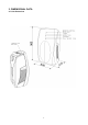
2.
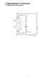
3.
4.
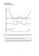
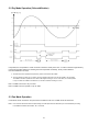
5. FUNCTION 5-1 Cool mode operation In cool mode, the operation of the compressor (COMP) and fan (FAN) are determined by the difference between the room temperature (RT) and the set point temperature (SPT) as in the graph above. notes: 1. In this graph, the FAN is operating in the "auto fan speed" setting. If the user has selected the low, medium or high fan speed, the FAN will run constantly at that speed only. 2.
5-2 Dry Mode Operation (Dehumidification) In Dry Mode, the unit operates in a mild cool mode to lower the umidity of the room. In order to maintain a high efficiency in the drying operation without over lowering the room temperature excessively, the dry mode is different from the Cool Mode in two ways. 1. The FAN is forced to operate at low speed only and is turned off with the COMP. 2. The unit operates in either "dry-on" state or the "dry-off" state. If RT=SPT, the unit will operate in "dry-off" state.
5-4 Protection Operations in Cool and Dry Modes 1. Evaporate coil defrost protection. The evaporate coil defrost protection can prevent the ice formation at the coil when the ambient temperature is low.
5-5 Sleep Function Room temperature is automatically controlled to compensate for body temperature variations while sleeping. This mode of operation is designed for maximal comfort in COOL mode. 5-6 Daily Timer Function Unit can be programmed to be ON and OFF automatically at preset time everyday, by using a remote controller. The resolutions of the ON/OFF timers are 10 min. 5-7 I-Feel Function This feature is provided if the unit is used together with a remote controller with the I-FEEL function.
5-8 Manual Unit Control and LED Indicators The push button switch and the LED indicators on the front of unit let the user to control the unit operation without a remote controller. Their operations are provided below. Led indicators: STAND BY OPERATION TIMER 1. Lights up when the air conditioner is connected to power and is ready to receive the R/C commands 2. Blinks continuosly in case of any thermistor failure 1. Lights up in operation mode (note: off in stanby mode) 2.
6.
7. TROUBLESHOOTING CHECK BEFORE AND AFTER TROUBLESHOOTING (A) Check power supply wiring. * WARNING: If the following troubleshooting must be done with power being supplied, be careful about any uninsulated live part that can cause ELECTRIC SHOCK. (B) Check power supply.
7-2 Some parts of air conditioner does not operate - Only fan does not run - Only compressor motor does not run 7-3 Air conditioner operate, but abnormalities are observed - Check remote control unit - Check fuse on PCB assy 16
7-4 Poor cooling 7-5 Excessive cooling 7-6 If a sensor is defective - TH1 (coil sensor) TH2 (room ambient teperature) are defective NOTE: Alarm signal (*) Standby lamp, on front side of the unit, will blink when the thermistor is defective. At the same time the unit operate only for ventilation.
7-7 Checking electrical components - Measurement of insulation resistance The insulation is in good condition if the resistence exceedes 1 MOhm a) power supply wires Clamp the earthed wire of the power supply wires with the lead clip of the insulation resiatance tester and measure the resistance by placing a probe on either of the power wires (fig.1). Then measure the resistance between the earthed wire and the other power wires (fig.1).
Via Varese, 90 - 21013 Gallarate - Va - Italy Tel. +39 0331 755111 - Fax +39 0331 776240 www.argoclima.