
Service Manual
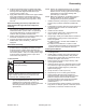

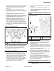
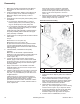

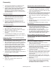


Table Of Contents

72
Reassembly
KohlerEngines.com 66 690 01 Rev. C
8. If securing upper brackets to top radiator mounts
were loosened, torque to 9.9 N·m (88 in. lb.).
9. If a pulse style fuel pump is used, install it to tapped
holes in cylinder 2 side, upper radiator support
bracket and torque two screws to 6.8-7.3 N·m
(60-65 in. lb.). Connect outlet line between pump
and carburetor and vacuum line to crankcase fi tting.
Secure with clamps.
Install Starter Adapter
1. Install starter adapter to crankcase, so cutout is
offset down and facing away from fl ywheel side.
Install mounting screws, and position clamp for
stator leads on upper screw. Torque screws to
15.3 N·m (135 in. lb.).
2. Place stator leads within clamp and close loop.
3. If violet B+ charge lead is separate from main
harness, secure it to wiring harness with a tie strap,
directly above clamp.
Install Starter Assembly
NOTE: Stator leads and rectifi er-regulator plug must be
above starter.
1. Mount starter to adapter plate using screws.
2. Make sure starter is square to fl ywheel, and torque
screws to 15.3 N·m (135 in. lb.).
3. Attach leads to appropriate starter solenoid
terminals.
4. To avoid damage or breakage, do not over-tighten
nut when attaching positive battery cable. Torque nut
to 6-9 N·m (53-79 in. lb.).
Install Lower Flywheel Cover, Rectifi er-Regulator
and Mounting Plate
1. Install/make sure small metal spacers are positioned
in mounting holes of lower fl ywheel cover.
2. Attach lower fl ywheel cover to cylinder 2 (oil fi lter)
side lower radiator support bracket, using M6 screws
and fl at washers. Finger tighten only at this time.
3. Align lower fl ywheel cover with cylinder 1 (starter)
side lower radiator support bracket holes. Position
rectifi er-regulator mounting plate, behind cover and
install remaining two screws or nuts and fl at
washers. Torque four fasteners to 9.9 N·m
(88 in. lb.). If screws and Timmerman nuts/clips are
used torque to 2.2-2.8 N·m (20-25 in. lb.).
4. If removed, mount rectifi er-regulator to plate with two
screws and attach connector plug.
Install Muffl er
1. Install new exhaust gaskets and attach muffl er and
mounting hardware. Torque screws to 9.9 N·m
(88 in. lb.).
2. Install nuts to exhaust studs. Torque nuts to
24.4 N·m (216 in. lb.).
Install Oil Filter and Fill Crankcase with Oil
NOTE: Make sure both oil drain plugs are installed and
torqued to specifi cations to prevent oil leakage.
1. Install oil drain plug(s). Torque plug(s) to 13.6 N·m
(10 ft. lb.). If oil drain valve is used, make sure valve
body is closed and cap is on.
2. Place new fi lter in shallow pan with open end up. Fill
with new oil until oil reaches bottom of threads. Allow
2 minutes for oil to be absorbed by fi lter material.
3. Apply a thin fi lm of clean oil to rubber gasket on oil
fi lter.
4. Refer to instructions on oil fi lter for proper
installation.
5. Fill crankcase with new oil. Level should be at top of
indicator on dipstick.
6. Reinstall oil fi ll cap/dipstick and tighten securely.
Install Coolant
1. Use equal parts of ethylene glycol (antifreeze) and
water only. Distilled or deionized water is
recommended, especially in areas where water
contains a high mineral content. Propylene glycol
based antifreeze is not recommended.
2. Fill cooling system, through radiator, with coolant
mix. Allow coolant to drain into lower areas. Fill
overfl ow reservoir midway between FULL and ADD
marks, then install radiator and reservoir caps.
Reconnect Battery and Spark Plug Leads
Connect leads to spark plugs. Reconnect positive
(+) battery lead fi rst, and negative (-) lead last when
connecting battery.
Testing Engine
It is recommended engine be operated on a test stand or
bench prior to installation in equipment.
1. Make sure all hardware is tightened, and hose
clamps are properly secured.
2. Set up engine on a test stand. Install an oil pressure
gauge. Start engine and check to be certain that oil
pressure (20 psi or more) is present. Run for 5-10
minutes between idle and mid-range.
3. Check all cooling system components and joint
connections for leaks.
4. Make sure maximum engine speed does not exceed
3750 RPM (no load). Adjust throttle, choke controls
and high speed stop as necessary. Refer to Fuel
System section.
5. Place throttle control into idle or slow position and
check low idle speed (RPM). Refer to Fuel System if
adjustment is required.
6. Stop engine.
7. Recheck oil and coolant levels. Oil level should be at
F mark on dipstick, and coolant level in reservoir
should be midway between ADD and FULL marks.
Add additional amounts as required.