
Service Manual
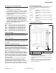
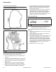
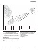
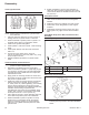
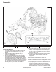
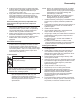

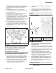
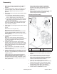
Table Of Contents

70
Reassembly
KohlerEngines.com 66 690 01 Rev. C
1. Make sure shoulder of fl ywheel hub and adjacent
face surface are clean and free of any nicks or
damage.
2. Install crankshaft pulley adapter onto fl ywheel hub,
so offset for pulley is out, and holes are aligned.
Make sure adapter rests squarely on face of
fl ywheel.
3. Assemble front and rear pulley halves placing shims
as indicated.
a. For a new belt: Assemble with 2 or 3 shims
between pulley halves, and remaining shim (if
any) on outside (front) of outer pulley half.
b. For a used belt: Assemble with 2 shims between
pulley halves and remaining shim(s) on outside
(front) of outer pulley half.
Install and snug pulley assembly. Final belt tension
and pulley assembly will be made after fan/upper
pulley assembly is installed.
4. Install upper fan mounting bracket to intake manifold
with screws.
Torque:
M6 Screws to 7.3 N·m (65 in. lb.)
M8 Screws to 24. 4 N·m (216 in. lb.)
By-pass hose and wires must be positioned within
cutout in intake manifold. Be careful not to pinch
harness wires between bracket and intake manifold
when tightening.
5. If disassembled, reassemble fan and pulley
assembly.
Make sure one fl at washer is placed between
bearings in hub. Other washer is located under front
nut. Torque fan/pulley/hub mounting screws to
6.8 N·m (60 in. lb.).
6. If fan shaft was removed from upper mounting
bracket, apply Loctite
®
242
®
to rear threads. Install
and torque rear nut to 15.8 N·m (140 in. lb.). Install
fan and pulley assembly onto fan shaft and upper
mounting bracket.
7. Apply Loctite
®
242
®
to front threads of fan shaft.
Install fl at washer and nut to secure. Torque nut to
15.8 N·m (140 in. lb.).
8. Carefully work belt into place on pulleys. Check belt
tension. There should be no more than 9.53 - 12.7
mm (3/8" - 1/2") belt defl ection per side with 10 lbs.
of applied tension.
If belt tension is low, remove belt and relocate a
shim from between pulley halves to outside (front).
Reinstall belt and recheck tension. Repeat
procedure until correct tension is reached. if shims
have all been moved to outside, and belt is still too
loose, replace belt.
When proper tension is obtained, individually
remove each capscrew, apply Loctite
®
242
®
to
threads of lower pulley and reinstall. Torque four
bolts in a criss-cross sequence to 24.3 N·m
(215 in. lb.).
9. Mount RH and LH lower radiator supports with cross
support bracket attached, to crankcase, using
screws. Snug screws only at this time.
Install Air Cleaner Assembly
External Engine Components
B
C
A
D
1
2
3
4
A Radiator Assembly B Mounting Bracket
C Air Cleaner Assembly D Torque Sequence
1. Install a new elbow adapter gasket onto carburetor
adapter.
2. Set air cleaner/mounting bracket assembly, with
hose and elbow attached, in position on engine.
Align all of mounting holes. Start and fi nger tighten
each of mounting screws. Make sure fuel line is
outside of main bracket when installed.
3. Torque elbow mounting screws to 7.3 N·m
(65 in. lb.). Then torque eight valve cover mounting
screws to 6.2 N·m (55 in. lb.) in sequence shown.
4. If removed, install rain cap and secure with clamp.
Check position of dust ejector, it should face
downward. Adjust end cap position as required.
5. Connect wires for audible alarm, if used.