
Service Manual
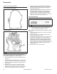
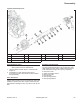
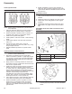
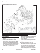
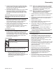

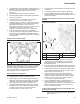
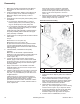
Table Of Contents

69
Reassembly
66 690 01 Rev. C KohlerEngines.com
3. Install breather reed and breather reed retainer onto
crankcase and secure with screw. Hold assembly in
line when tightening. Torque screw to 3.9 N·m
(35 in. lb.).
4. Install breather fi lter into cavity in crankcase.
5. Carefully install breather cover gasket and breather
cover onto crankcase.
6. Install and torque four breather cover screws to
7.3 N·m (65 in. lb.) in sequence shown.
7. Install pipe plug or Oil Sentry
™
switch (as equipped),
into tapped breather port if removed earlier. Apply
pipe sealant with Tefl on
®
(Loctite
®
592™ or
equivalent) to threads. Torque to 4.5 N·m (40 in. lb.).
If Oil Sentry
™
switch is mounted to side of
crankcase, torque switch to 12.4 N·m (110 in. lb.).
8. If vacuum fi tting was removed from crankcase
(vacuum fuel pump), apply pipe sealant with Tefl on
®
(Loctite
®
592™ or equivalent) to threads of fi tting
and install. With crankcase upright, fi tting must point
to 1:30 position.
Reinstall Coolant Drain Plugs
Coolant Drain Plug Details
A
A
A Coolant Drain Plug
Reinstall brass coolant drain plugs in sides of crankcase,
(and also cylinder head plugs, if removed during head
servicing). Apply pipe sealant with Tefl on® (Loctite
®
592™ or equivalent) to threads and reinstall plugs.
Torque plugs to 36.7 N·m (325 in. lb.).
Install Carburetor and Adapter
1. If separated, install breather tube to breather cover.
2. Install carburetor gasket on intake manifold.
3. Attach longer ends of throttle linkage and spring to
carburetor (if disconnected previously), then install
carburetor onto intake manifold. Install and torque
mounting screws to 6.2-7.3 N·m (55-65 in. lb.).
4. If adapter was separated from carburetor, install a
new gasket and mount adapter with breather hose
connection port facing rear. Install and torque
mounting screws to 7.3 N·m (65 in. lb.).
5. Connect upper end of breather hose to fi tting on rear
of adapter.
6. Connect long end of choke linkage to carburetor.
7. If a mechanical fuel pump is used, install fuel line
between outlet of fuel pump and carburetor inlet, and
secure with clamps.
Install External Governor Controls and Main Control
Bracket
Control Panel Details
D
C
E
A
B
A Control Panel B Choke Lever
C Governor Lever Nut D Governor Lever
E Governor Spring
1. Install governor lever onto governor cross shaft. If
separated, connect throttle link to governor lever
with plastic bushing. Hook dampening spring into
small (middle) hole.
2. Move governor lever TOWARDS carburetor as far as
it will go (wide open throttle) and hold in this position.
3. Insert a nail into hole in cross shaft and rotate shaft
COUNTERCLOCKWISE as far as it will turn. Then
torque nut to 6.8 N·m (60 in. lb.).
4. Connect choke lever of main control bracket to
choke linkage from carburetor. Mount main control
bracket to cylinder heads with four screws. Torque
screws to 10.7 N·m (95 in. lb.) into new holes, or
7.3 N·m (65 in. lb.) into used holes.
5. Connect dampening spring to throttle lever. Hook
governor spring from throttle control bracket in
appropriate governor lever hole, as indicated in chart
below. Note that hole positions are counted from
pivot point of governor lever.
Install Lower Crankshaft Pulley, Pulley Adapter, and
Cooling Fan Assembly
NOTE: Do not assemble lower pulley with belt between
pulley halves, as pinching of belt or damage to
pulley can occur.