
Service Manual
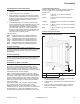
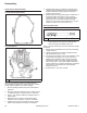
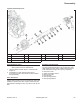
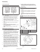
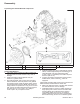
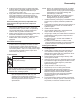

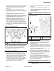
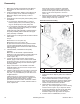
Table Of Contents

67
Reassembly
66 690 01 Rev. C KohlerEngines.com
8. Position thermostat housing on gasket and intake
manifold. Notch in manifold, gasket and thermostat
housing must all be aligned. Install and torque
screws to 9.9 N·m (88 in. lb.).
9. Apply rubber lubricant to inside end of upper radiator
hose, and install hose to thermostat housing, if
separated for servicing. Secure with clamp. Make
sure tangs of clamp point toward cylinder 1, away
from fan.
Install Coolant By-pass Hose (If separated from
intake manifold through individual component
servicing)
1. If connector fi tting for by-pass hose was removed
from manifold, reinstall it at this time. Apply pipe
sealant with Tefl on
®
(Loctite
®
592™ or equivalent)
onto threads and tighten, so fi tting faces/points
toward 2 side, long intake manifold screw.
2. Attach coolant by-pass hose to fi ttings in water pump
and intake manifold. Secure with clamps.
3. Connect wire leads to temperature warning switch,
audible alarm, and/or Oil Sentry
™
switch, as
equipped.
Install Stator Assembly
1. Place a small amount of pipe sealant with Tefl on
®
(Loctite
®
592™ or equivalent) into holes for stator
mounting screws. Position stator assembly onto
mounting studs so leads are at bottom, and directed
out toward cylinder 1 side, in 3 o'clock position. Align
mounting holes and install screws. Torque each
screw to 6.2 N·m (55 in. lb.).
Install Flywheel
CAUTION
Damaging Crankshaft and Flywheel can
cause personal injury.
Using improper procedures can lead to broken
fragments. Broken fragments could be thrown from
engine. Always observe and use precautions and
procedures when installing fl ywheel.
NOTE: Before installing fl ywheel make sure crankshaft
taper and fl ywheel hub are clean, dry, and
completely free of lubricants. Presence of
lubricants can cause fl ywheel to be overstressed
and damaged when screw is torqued to
specifi cations.
NOTE: Always use a fl ywheel strap wrench or holding
tool to hold fl ywheel when tightening fl ywheel
fastener. Do not use any type of bar or wedge to
hold fl ywheel, as component damage and
personal injury could result.
NOTE: Make sure fl ywheel key is installed properly in
keyway. Flywheel can become cracked or
damaged if key is improperly installed.
1. Install woodruff key into keyway of crankshaft. Make
sure that key is properly seated and parallel with
shaft.
2. Thread starter mounting bolts into hub of fl ywheel, or
use fl ywheel puller to serve as a handle and set
fl ywheel in place.
3. Install screw and washer.
4. Use a fl ywheel holding tool to hold fl ywheel and
torque screw to 66.4 N·m (49 ft. lb.).
5. Using a light, visually check that suffi cient clearance
exists between cooling system components and
bottom of fl ywheel.
● If clearance is OK, continue with installation of
ignition modules.
● If clearance is insuffi cient or contact is noted,
remove fl ywheel and adjust as required. Reinstall
fl ywheel and recheck for adequate clearance.
Install Ignition Modules
1. Rotate fl ywheel magnet away from ignition module
mounting bosses.
2. Install ignition modules, with ground terminal out,
onto crankcase mounting bosses, using screws.
Slide ignition modules away from fl ywheel as far as
possible, and tighten four screws.
3. Rotate fl ywheel to position magnet directly under
one of ignition modules.
4. Insert a 0.25 mm (0.010 in.) fl at feeler gauge or shim
stock between magnet and ignition module. Loosen
screws enough to allow magnet to pull module
against feeler gauge.
5. Torque screws to 4.0 N·m (35 in. lb.).
6. Repeat steps 3 to 5 for other ignition module.
7. Rotate fl ywheel back and forth checking for
clearance between magnet and ignition modules.
Make sure magnet does not strike modules.
Recheck gap with a feeler gauge and readjust if
necessary. Final air gap: 0.203/0.305 mm
(0.008/0.012 in.).
8. Connect kill leads to ignition modules. Push (bend)
loop portion of clamp on cylinder 1 side back, as far
as possible, for maximum clearance from fan.