
Service Manual
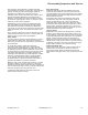

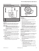


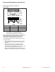
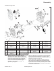
Table Of Contents

54
Disassembly/Inspection and Service
KohlerEngines.com 66 690 01 Rev. C
5. After torquing, rotate gear and check for freedom of
movement. Make sure there is no binding. If binding
occurs, loosen screws, reposition pump, retorque
screws and recheck movement.
Remove Oil Pump (Style B)
Oil pump is mounted inside closure plate. If service is
required, continue with Disassembly, Inspection, and
Reassembly.
Disassembly
1. Remove screws.
2. Lift oil pump assembly from closure plate. Remove
outer gerotor gear from closure plate.
3. Ensure ball and spring remain installed in pressure
relief hole of closure plate. If ball and spring fall out
of pressure relief hole, see reassembly for correct
installation.
4. Remove oil pump cover O-ring from groove in
closure plate.
Inspection
Inspect oil pump housing, gear, and rotors for nicks,
burrs, wear, or any visible damage. Inspect oil pump
cover O-ring for cuts, nicks, or any visible damage. If any
parts are worn or damaged, replace oil pump assembly
and/or O-ring. Check oil pickup screen for damage or
restriction, replace if necessary.
Reassembly
1. Lubricate outer gerotor gear with oil. Install outer
gerotor gear through shaft of oil pump, around inner
gerotor gear. Matching molding dots on inner and
outer gerotor gears is not necessary and will not
affect oil pump effi ciency.
2. Reinstall ball, then spring into pressure relief hole in
closure plate.
3. Reinstall O-ring into groove in closure plate; make
sure it is fully seated in groove.
4. Install oil pump inserting center shaft into
corresponding recess in closure plate. Apply
consistent downward pressure to oil pump cover,
compressing oil pressure relief spring and start
screws. Secure oil pump by torquing screws (in no
specifi c sequence) to 7.9 N·m (70 in. lb.).
5. After torquing, rotate gear and check for freedom of
movement. Make sure there is no binding. If binding
occurs, loosen screws, reposition pump, retorque
screws and recheck movement.
Remove Camshaft
Remove camshaft and shims.
Remove Connecting Rods with Pistons and Rings
NOTE: If a carbon ridge is present at top of either
cylinder bore, use a ridge reamer tool to remove
it before attempting to remove piston.
NOTE: Cylinders are numbered on crankcase. Use
numbers to mark each end cap and connecting
rod/piston assembly for reassembly later. Do not
mix end caps and connecting rods.
1. Remove screws securing closest connecting rod end
cap. Remove end cap.
2. Carefully remove connecting rod and piston
assembly from cylinder bore.
3. Repeat above procedure for other connecting rod
and piston assembly.
Connecting Rods
Offset, stepped-cap connecting rods are used in all
these engines.
Inspection and Service
Check bearing area (big end) for excessive wear, score
marks, running and side clearances. Replace rod and
cap if scored or excessively worn.
Service replacement connecting rods are available in
STD crankpin size and 0.25 mm (0.010 in.) undersize.
An 0.25 mm (0.010 in.) undersized rod can be identifi ed
by a drilled hole located in lower end of rod shank.
Always refer to appropriate parts information to ensure
correct replacements are used.
Inspection
Piston and Rings Components and Details
A
C
J
B
Style A
D
E
F
G
I
H
Style B
F
E
D
H
G
A Piston Ring B End Gap
C Identifi cation Mark D Piston
E
Top Compression
Ring
F
Middle Compression
Ring
G Rails H Expander
I
Oil Control Ring
(3 Piece)
J Dye Colored Stripe