
Service Manual
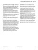

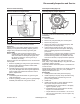


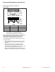
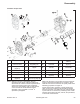
Table Of Contents

53
Disassembly/Inspection and Service
66 690 01 Rev. C KohlerEngines.com
Governor Gear Assembly
Governor Shaft Press Depth Details
C
B
A
A Gear Shaft
B 19.40 mm (0.7638 in.)
C 34.0 mm (1.3386 in.) 33.5 mm (1.3189 in.)
Governor gear assembly is located inside closure plate.
If service is required, refer to these procedures.
Inspection
Inspect governor gear teeth. Replace gear if it is worn,
chipped, or if any teeth are missing. Inspect governor
weights. They should move freely in governor gear.
Disassembly
NOTE: Governor gear is held onto shaft by small
molded tabs in gear. When gear is removed from
shaft, these tabs are destroyed and gear must
be replaced. Therefore, remove gear only if
absolutely necessary.
Governor gear must be replaced once it is removed from
closure plate.
1. Remove regulating pin and governor gear assembly.
2. Remove locking tab thrust washer located under
governor gear assembly.
3. Carefully inspect governor gear shaft and replace it
only if it is damaged. After removing damaged shaft,
press or lightly tap replacement shaft into closure
plate to depth shown.
Reassembly
1. Install locking tab thrust washer on governor gear
shaft with tab down.
2. Position regulating pin within governor gear/fl yweight
assembly and slide both onto governor shaft.
Oil Pump Assembly (Style A)
Oil Pump (Style A) Torque Sequence
1
2
Oil pump is mounted inside of closure plate. If service
is required, continue with Disassembly, Inspection, and
Reassembly.
Disassembly
1. Remove screws.
2. Remove oil pump assembly from closure plate.
3. Remove oil pump rotor.
4. Remove oil pickup by unhooking locking clip, and
pulling it free from oil pump body.
5. If relief valve is similar to shown, drive out pin to
remove oil pressure relief valve piston and spring.
Refer to following inspection and reassembly
procedures.
If relief valve is a one-piece style, staked to oil pump
housing removal should not be attempted, nor is
internal servicing possible. If a problem with relief
valve is encountered, oil pump should be replaced.
Inspection
Inspect oil pump housing, gear, and rotors for nicks,
burrs, wear, or any visible damage. If any parts are worn
or damaged, replace oil pump.
Inspect oil pressure relief valve piston. It should be free
of nicks or burrs.
Check spring for wear or distortion. Free length of spring
should be approximately 47.4 mm (1.8 in.). Replace
spring if it is distorted or worn.
Reassembly
1. Install pressure relief valve piston and spring.
2. Install oil pickup to oil pump body. Lubricate O-ring
with oil and make sure it remains in groove as
pickup is being installed.
3. Install rotor.
4. Install oil pump body to closure plate and secure
with screws. Torque screws as follows:
a. Install fastener into screw location 1 and lightly
tighten to position pump.
b. Install fastener into screw location 2 and fully
torque to recommended value.
c. Torque fastener in screw location 1 to 10.7 N·m
(95 in. lb.) into new holes, or 6.7 N·m (60 in. lb.)
into used holes.