
Service Manual


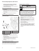
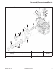

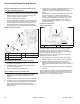
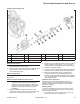
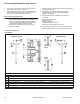
Table Of Contents

50
Disassembly/Inspection and Service
KohlerEngines.com 66 690 01 Rev. C
2. Lay a rag or shop towel on table of drill press and
place lifter, open end up, on towel.
3. Lower chucked push rod until it contacts plunger in
lifter. Slowly pump plunger two or three times to
force oil out of feed hole in side of lifter.
Disassemble Cylinder Heads
NOTE: These engines use a valve stem seal on intake
and exhaust valves. Serial No. 3422000010 and
lower used a seal on intake side only. Always
use new seals when valves are removed from
cylinder head. Replace seals if they are
deteriorated or damaged in any way. Never
reuse an old seal.
1. Remove screws, rocker arms pivots and rocker arms
from cylinder head(s).
2. Compress valve springs using a valve spring
compressor and remove valve spring keepers.
Remove compressor.
3. With keepers taken out following items can be
removed.
● Valve spring retainers.
● Valve springs.
● Valve spring caps.
● Intake and exhaust valves.
● Valve stem seals (intake valve only).
4. Repeat above procedure for other cylinder head. Do
not interchange parts from 1 cylinder head to other.
Inspection and Service
Valve Details
EXHAUST VALVE INTAKE VALVE
EXHAUST
INSERT
INTAKE
INSERT
H
H
G
G
E
E
F
F
A
A
C
D
D
B
B
Dimension Intake Exhaust
A Seat Angle 89° 89°
B Insert O.D. 36.987/37.013 mm (1.4562/1.4572 in.) 32.987/33.013 mm (1.2987/1.2997 in.)
C Guide Depth 4 mm (0.1575 in.) 6.5 mm (0.2559 in.)
D Guide I.D. 7.038/7.058 mm (0.2771/0.2779 in.) 7.038/7.058 mm (0.2771/0.2779 in.)
E Valve Head Diameter 33.37/33.63 mm (1.3138/1.3240 in.) 29.37/29.63 mm (1.1563/1.1665 in.)
F Valve Face Angle 45° 45°
G Valve Margin (Min.) 1.5 mm (0.0591 in.) 1.5 mm (0.0591 in.)
H Valve Stem Diameter 6.982/7.000 mm (0.2749/0.2756 in.) 6.970/6.988 mm (0.2744/0.2751 in.)