
Service Manual
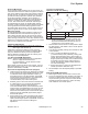
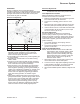
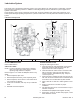

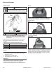
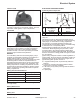
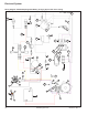
Table Of Contents

25
Governor System
66 690 01 Rev. C KohlerEngines.com
GOVERNOR
Engine is equipped with a centrifugal fl yweight
mechanical governor. It is designed to hold engine speed
constant under changing load conditions. Governor gear/
fl yweight mechanism is mounted inside closure plate
and is driven off gear on camshaft.
Governor Components
A
B
C
E
F
D
A Flyweight B Regulating Pin
C Cross shaft D Governor Lever
E Throttle Linkage F Throttle Lever
● Centrifugal force acting on rotating governor gear
assembly causes fl yweights to move outward as
speed increases. Governor spring tension moves
them inward as speed decreases.
● As fl yweights move outward, they cause regulating pin
to move outward.
● Regulating pin contacts tab on cross shaft causing
shaft to rotate.
● One end of cross shaft protrudes through crankcase.
Rotating action of cross shaft is transmitted to throttle
lever of carburetor through external linkage.
● When engine is at rest, and throttle is in fast position,
tension of governor spring holds throttle plate open.
When engine is operating, governor gear assembly is
rotating. Force applied by regulating pin, against cross
shaft, tends to close throttle plate. Governor spring
tension and force applied by regulating pin balance
each other during operation, to maintain engine
speed.
● When load is applied and engine speed and governor
gear speed decreases, governor spring tension moves
governor arm to open throttle plate wider. This allows
more fuel into engine, increasing engine speed. As
speed reaches governed setting, governor spring
tension and force applied by regulating pin will again
offset each other to hold a steady engine speed.
Governor Adjustments
NOTE: Do not tamper with governor setting. Overspeed
is hazardous and could cause personal injury.
Initial Adjustment Procedure
Make this adjustment whenever governor lever is
loosened or removed from cross shaft.
1. Make sure throttle linkage is connected to governor
lever and throttle lever on carburetor.
2. Loosen hex nut holding governor lever to cross
shaft.
3. Move governor lever towards carburetor as far as it
will move (wide open throttle) and hold in position.
4. Insert a nail into hole on cross shaft and rotate shaft
counterclockwise as far as it will turn, then torque
hex nut to 6.8 N·m (60 in. lb.).
Sensitivity Adjustment
Governor sensitivity is adjusted by repositioning
governor spring in holes on governor lever. If speed
surging occurs with a change in engine load, governor
is set too sensitive. If a big drop in speed occurs when
normal load is applied, governor should be set for
greater sensitivity.
1. To increase sensitivity, move spring closer to
governor cross shaft.
2. To decrease sensitivity, move spring away from
governor cross shaft.
High Speed RPM Adjustment
NOTE: When throttle and choke control cables are
routed side-by-side, especially under a single
clamp, there must be a small gap between
cables to prevent internal binding. After high-
speed setting has been complete, check that
there is gap of at least 0.5 mm (0.020 in.)
between control cables.
1. With engine running, move throttle control to fast.
Use a tachometer to check RPM speed.
2. Loosen lock nut on high speed adjusting screw. Turn
screw outward to decrease, or inward to increase
RPM speed. Check RPM with a tachometer.
3. When desired RPM speed is obtained, retighten lock
nut.