LH630, LH640, LH685, LH690, LH750, LH755 Service Manual IMPORTANT: Read all safety precautions and instructions carefully before operating equipment. Refer to operating instruction of equipment that this engine powers. Ensure engine is stopped and level before performing any maintenance or service.
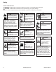
Safety SAFETY PRECAUTIONS WARNING: A hazard that could result in death, serious injury, or substantial property damage. CAUTION: A hazard that could result in minor personal injury or property damage. NOTE: is used to notify people of important installation, operation, or maintenance information. WARNING Explosive Fuel can cause fires and severe burns. Do not fill fuel tank while engine is hot or running. Gasoline is extremely flammable and its vapors can explode if ignited.
Maintenance MAINTENANCE INSTRUCTIONS WARNING Accidental Starts can cause severe injury or death. Disconnect and ground spark plug lead(s) before servicing. Before working on engine or equipment, disable engine as follows: 1) Disconnect spark plug lead(s). 2) Disconnect negative (–) battery cable from battery.
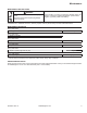
Maintenance OIL RECOMMENDATIONS We recommend use of Kohler oils for best performance. Other high-quality detergent oils (including synthetic) of API (American Petroleum Institute) service class SJ or higher are acceptable. Select viscosity based on air temperature at time of operation as shown in table below. STORAGE If engine will be out of service for 2 months or more follow procedure below. 1. Add Kohler PRO Series fuel treatment or equivalent to fuel tank.
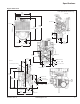
Specifications Engine Dimensions Dimensions in millimeters. Inch equivalents shown in (). 440.00 (17.323) Oil Filter Side 23 Rain Cap Removal (0.906) Optional Oil Fill Fuel Pump 622.54 (24.509) Overall without Rain Cap 673.70 (26.524) Overall 152.08 (5.987) Oil Drain 38.00 (1.496) 2X 184.20 (7.252) 143.25 (5.640) 127.90 (5.035) CL Mounting Hole CL Mounting Hole 175.41 (6.906) C L Mounting Hole "A" PTO Side 458.49 (18.051) Overall Flywheel End 2X 60° 2X 45° 2X 297.47 (1.711) 142.
Specifications ENGINE IDENTIFICATION NUMBERS Kohler engine identification numbers (model, specification and serial) should be referenced for efficient repair, ordering correct parts, and engine replacement. Model . . . . . . . . . . . . . . . . . . . . . LH630 Liquid Cooled Horizontal Shaft Numerical Designation Specification . . . . . . . . . . . . . . . LH630-0001 Serial . . . . . . . . . . . . . . . . . . . . .
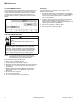
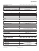
Specifications TORQUE SPECIFICATIONS3,5 LH630 LH640 Electric Starter Starter Thru Bolt Starter Mounting Screw Starter Brush Holder Fastener Starter Solenoid Fastener Starter Solenoid Positive (+) Brush Lead Retaining Nut Fan/Flywheel Rear Fan Shaft to Mounting Bracket Nut Front Fan Assembly to Fan Shaft Nut Fan/Pulley/Hub Assembly Fastener Flywheel Retaining Screw Lower Flywheel Cover Mounting Screw Lower Pulley Mounting Screw LH685 LH690 15.8 N·m (140 in. lb.) 15.8 N·m (140 in. lb.) 6.8 N·m (60 in.
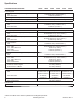
Specifications CLEARANCE SPECIFICATIONS3 LH630 LH640 LH685 LH690 LH750 Connecting Rod Connecting Rod-to-Crankpin Running Clearance New Max. Wear Limit Connecting Rod-to-Crankpin Side Clearance Connecting Rod-to-Piston Pin Running Clearance 0.043/0.068 mm (0.0016/0.0026 in.) 0.083 mm (0.0032 in.) 0.26/0.63 mm (0.0102/0.0248 in.) 0.015/0.028 mm (0.0006/0.0011 in.) Crankcase Governor Cross Shaft Bore I.D. New Max. Wear Limit 8.025/8.075 mm (0.3159/0.3179 in.) 8.088 mm (0.3184 in.
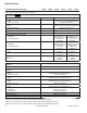
Specifications CLEARANCE SPECIFICATIONS3 LH630 LH640 Governor Governor Cross Shaft to Crankcase Running Clearance Governor Cross Shaft O.D. New Max. Wear Limit Governor Gear Shaft O.D. New Max. Wear Limit Governor Gear Shaft -to-Governor Gear Running Clearance LH685 LH690 LH750 LH755 0.025/0.126 mm (0.0009/0.0049 in.) 7.949/8.000 mm (0.3129/0.3149 in.) 7.936 mm (0.3124 in.) 5.990/6.000 mm (0.2358/0.2362 in.) 5.977 mm (0.2353 in.) 0.090/0.160 mm (0.0035/0.0063 in.
Specifications CLEARANCE SPECIFICATIONS3 LH630 LH640 LH685 LH690 LH750 LH755 Piston, Piston Rings, and Piston Pin (continued) Piston Style B Piston-to-Piston Pin Piston Pin Bore I.D. New Max. Wear Limit Piston Pin O.D. New Max. Wear Limit Top Compression Ring-to-Groove Side Clearance Middle Compression Ring-to-Groove Side Clearance Oil Control Ring-to-Groove Side Clearance Top Compression Ring End Gap New Bore 0.006/0.017 mm (0.0002/0.0007 in.) 17.006/17.012 mm (0.6695/0.6698 in.) 17.025 mm (0.
Specifications GENERAL TORQUE VALUES English Fastener Torque Recommendations for Standard Applications Bolts, Screws, Nuts and Fasteners Assembled Into Cast Iron or Steel Grade 2 or 5 Fasteners Into Aluminum Size Grade 2 Tightening Torque: N·m (in. lb.) ± 20% 8-32 2.3 (20) 10-24 3.6 (32) 10-32 3.6 (32) 1/4-20 7.9 (70) 1/4-28 9.6 (85) 5/16-18 17.0 (150) 5/16-24 18.7 (165) 3/8-16 29.4 (260) 3/8-24 33.9 (300) Grade 5 Grade 8 2.8 (25) 4.5 (40) 4.5 (40) 13.0 (115) 15.8 (140) 28.3 (250) 30.
Tools and Aids Certain quality tools are designed to help you perform specific disassembly, repair, and reassembly procedures. By using these tools, you can properly service engines easier, faster, and safer! In addition, you’ll increase your service capabilities and customer satisfaction by decreasing engine downtime. Here is a list of tools and their source. SEPARATE TOOL SUPPLIERS Kohler Tools Contact your local Kohler source of supply. SE Tools 415 Howard St.
Tools and Aids TOOLS Description Hydraulic Valve Lifter Tool For removing and installing hydraulic lifters. Ignition System Tester For testing output on all systems, including CD. Inductive Tachometer (Digital) For checking operating speed (RPM) of an engine. Offset Wrench (K and M Series) For removing and reinstalling cylinder barrel retaining nuts. Oil Pressure Test Kit For testing/verifying oil pressure on pressure lubricated engines.
Tools and Aids FLYWHEEL HOLDING TOOL ROCKER ARM/CRANKSHAFT TOOL A flywheel holding tool can be made out of an old junk flywheel ring gear and used in place of a strap wrench. 1. Using an abrasive cut-off wheel, cut out a six tooth segment of ring gear as shown. 2. Grind off any burrs or sharp edges. 3. Invert segment and place it between ignition bosses on crankcase so tool teeth engage flywheel ring gear teeth.
Troubleshooting TROUBLESHOOTING GUIDE When troubles occur, be sure to check simple causes which, at first, may seem too obvious to be considered. For example, a starting problem could be caused by an empty fuel tank. Some general common causes of engine troubles are listed below and vary by engine specification. Use these to locate causing factors. Engine Cranks But Will Not Start ● Battery connected backwards. ● Blown fuse. ● Carburetor solenoid malfunction. ● Choke not closing.
Troubleshooting Engine Loses Power ● Dirty air cleaner element. ● Engine overheated. ● Excessive engine load. ● Restricted exhaust. ● Faulty spark plug(s). ● High crankcase oil level. ● Incorrect governor setting. ● Low battery. ● Low compression. ● Low crankcase oil level. ● Quality of fuel (dirt, water, stale, mixture). Engine Uses Excessive Amount of Oil ● Loose or improperly torqued fasteners. ● Blown head gasket/overheated. ● Breather reed broken. ● Clogged, broken, or inoperative crankcase breather.
Troubleshooting CRANKCASE VACUUM TEST WARNING WARNING Carbon Monoxide can cause severe nausea, fainting or death. Avoid inhaling exhaust fumes. Engine exhaust gases contain poisonous carbon monoxide. Carbon monoxide is odorless, colorless, and can cause death if inhaled. Rotating Parts can cause severe injury. Stay away while engine is in operation. Keep hands, feet, hair, and clothing away from all moving parts to prevent injury. Never operate engine with covers, shrouds, or guards removed.
Troubleshooting COMPRESSION TEST For Command Twins: A compression test is best performed on a warm engine. Clean any dirt or debris away from base of spark plug(s) before removing them. Be sure choke is off, and throttle is wide open during test. Compression should be at least 160 psi and should not vary more than 15% between cylinders. All other models: These engines are equipped with an automatic compression release (ACR) mechanism.
Air Cleaner/Intake AIR CLEANER These systems are CARB/EPA certified and components should not be altered or modified in any way. Heavy-Duty Air Cleaner Components C B Hot Parts can cause severe burns. Do not touch engine while operating or just after stopping. E Never operate engine with heat shields or guards removed. D Air Cleaner Housing Retaining Clip End Cap WARNING F A A C E BREATHER TUBE Ensure both ends of breather tube are properly connected.
Fuel System Typical carbureted fuel system and related components include following: ● Fuel tank. ● In-line fuel filter. ● Fuel pump. ● Carburetor. ● Fuel lines. Fuel from tank is moved through in-line filter and fuel lines by fuel pump. Fuel then enters carburetor fl oat bowl and is drawn into carburetor body and mixed with air. This fuel-air mixture is then burned in engine combustion chamber. FUEL RECOMMENDATIONS Refer to Maintenance.
Fuel System CARBURETOR WARNING Explosive Fuel can cause fires and severe burns. Do not fill fuel tank while engine is hot or running. Gasoline is extremely flammable and its vapors can explode if ignited. Store gasoline only in approved containers, in well ventilated, unoccupied buildings, away from sparks or flames. Spilled fuel could ignite if it comes in contact with hot parts or sparks from ignition. Never use gasoline as a cleaning agent.
Fuel System Troubleshooting-Carburetor Related Causes Condition Engine starts hard, runs rough, or stalls at idle speed. Engine runs rich (indicated by black, sooty exhaust smoke, misfiring, loss of speed and power, governor hunting, or excessive throttle opening). Engine runs lean (indicated by misfiring, loss of speed and power, governor hunting, or excessive throttle opening). Fuel leaks from carburetor. Possible Cause Low idle fuel mixture (some models)/ speed improperly adjusted.
Fuel System Slow and Mid-Range At low speeds engine operates only on slow circuit. As a metered amount of air is drawn through slow air bleed jets, fuel is drawn through main jet and further metered through slow jet. Air and fuel are mixed in body of slow jet and exit to idle progression (transfer port) chamber. From idle progression chamber, air fuel mixture is metered through idle port passage. At low idle air/fuel mixture is controlled by setting of idle fuel adjusting screws.
Fuel System Carburetor is now disassembled for appropriate cleaning and installation of parts in overhaul kit. See instructions provided with repair kits for more detailed information. Carburetor Servicing WARNING Explosive Fuel can cause fires and severe burns. Do not fill fuel tank while engine is hot or running. Gasoline is extremely flammable and its vapors can explode if ignited. Store gasoline only in approved containers, in well ventilated, unoccupied buildings, away from sparks or flames.
Governor System GOVERNOR Engine is equipped with a centrifugal flyweight mechanical governor. It is designed to hold engine speed constant under changing load conditions. Governor gear/ flyweight mechanism is mounted inside closure plate and is driven off gear on camshaft.
Lubrication System This engine uses a full pressure lubrication system. This system delivers oil under pressure to crankshaft, camshaft and connecting rod bearing surfaces. In addition to lubricating bearing surfaces, lubrication system supplies oil to hydraulic valve lifters. A high-efficiency gerotor pump is located in closure plate. Oil pump maintains high oil flow and oil pressure, even at low speeds and high operating temperatures.
Lubrication System 9. Dispose of used oil and filter in accordance with local ordinances. OIL SENTRY™ (if equipped) This switch is designed to prevent engine from starting in a low oil or no oil condition. Oil Sentry™ may not shut down a running engine before damage occurs. In some applications this switch may activate a warning signal. Read your equipment manuals for more information. Oil Sentry™ pressure switch is installed in breather cover.
Electrical System Normal SPARK PLUGS CAUTION Electrical Shock can cause injury. Do not touch wires while engine is running. Spark Plug Component and Details A B Plug taken from an engine operating under normal conditions will have light tan or gray colored deposits. If center electrode is not worn, plug can be set to proper gap and reused. Worn D C A C Wire Gauge Ground Electrode B D Spark Plug Gap NOTE: Do not clean spark plug in a machine using abrasive grit.
Electrical System ELECTRONIC IGNITION SYSTEMS Ignition System Components Carbon Fouled F A E B Soft, sooty, black deposits indicate incomplete combustion caused by a restricted air cleaner, over rich carburetion, weak ignition, or poor compression. Overheated C A C E Chalky, white deposits indicate very high combustion temperatures. This condition is usually accompanied by excessive gap erosion.
Electrical System AG AF AD AE AB W AC AS U O J R S AR P A E D Q I C B F M G L T K H I N V T L AA Y X V AD Z AQ AP AH AI X AO AK AJ AL AM V AK V AN AJ Wiring Diagram-15/20/25 Amp Regulated Battery Charging System with Fixed Timing 30 KohlerEngines.com 66 690 01 Rev.
Electrical System A Accessory (Yellow) B E Ignition Kill (White) F I M Q Battery Run Starter Solenoid Tang J N R Battery (Red) Key Switch Ground (Black) Accessory Yellow Starter Assembly C Starter (Blue/Red) D Run (Red) G Ground H Starter K O S Key Switch Connector Fuse L P T White W Carburetor X Ignition Kill Starter Solenoid Stud Red Intake Manifold Screw U Black V Y Ground (Black) Z Oil SentryTM Light AA Carburetor Solenoid AC Regulator Connector AD AC AE B+ AF S
Electrical System Test for Spark NOTE: If 2 testers are available, testing can be performed simultaneously for both cylinders. However, if only 1 tester is available, 2 individual tests must be performed. Side not being tested must have spark plug lead connected or grounded. Do not crank engine or perform tests with 1 spark plug lead disconnected and not grounded, or permanent system damage may occur. 1. With engine stopped, disconnect 1 spark plug lead.
Electrical System Condition OK (green) light comes on and stays steady. NOTE: A flashing LOW light can also occur as a result of an inadequate ground lead connection. Make certain connection location is clean and clamp is secure. Other lights come on. Conclusion 20/25 amp 15 amp Disconnect tester black lead Part is good and may be used. attached to 1 AC terminal and reconnect it to other AC terminal. Repeat test. If OK (green) light comes on again, part is good and may be used.
Starter System NOTE: Do not crank engine continuously for more than 10 seconds. Allow a 60 second cool down period between starting attempts. Failure to follow these guidelines can burn out starter motor. NOTE: If engine develops sufficient speed to disengage starter but does not keep running (a false start), engine rotation must be allowed to come to a complete stop before attempting to restart engine.
Starter System Solenoid Shift Starter Components Starter Disassembly NOTE: Do not reuse old retainer. NOTE: Do not soak armature or use solvent when cleaning. Wipe clean using a soft cloth, or use compressed air. 1. Remove hex nut and disconnect positive (+) brush lead/bracket from solenoid terminal. 2. Remove screws securing solenoid to starter. 3. Unhook plunger pin from drive lever. Remove gasket from recess in housing. 4. Remove thru (larger) bolts. 5.
Starter System Armature Components and Details A B A Commutator O.D. B Mica Insulation C D C E Insulation Check Continuity Check E D Armature Coil 1. Clean and inspect commutator (outer surface). Mica insulation must be lower than commutator bars (undercut) to ensure proper operation of commutator. 2. Use an ohmmeter set to Rx1 scale. Touch probes between 2 different segments of commutator, and check for continuity. Test all segments. Continuity must exist between all or armature is bad. 3.
Starter System c. Install brush springs and snap on retainer caps. d. Hold starter assembly vertically on end housing, and carefully place tool (with extension) and assembled original brush holder assembly onto end of armature shaft. Slide brush holder assembly down into place around commutator, install positive (+) brush lead grommet in cutout of frame. 11. Install end cap onto armature and frame, aligning thin raised rib in end cap with corresponding slot in grommet of positive (+) brush lead. 12.
Cooling System WARNING Hot liquid can cause severe burns. Do not loosen radiator cap while engine is operating or warm to touch. When it is necessary to open cooling system at radiator cap, shut off engine and remove filler cap only when cool enough to touch with bare hands. Slowly loosen cap to first stop to relieve pressure before removing completely. This section covers operation and servicing of liquid cooling system.
Cooling System Add coolant to overflow reservoir as required, which is a 50/50 mixture of ethylene glycol and water (distilled or deionized water is recommended). Drain Cooling System Radiator Drain Plug Details A A Radiator Drain Plug 1. Ensure engine is cool. When radiator is cool to touch, slowly loosen radiator cap to first stop and allow any pressure to bleed off. Then loosen it fully and remove it. Loosen/remove radiator drain plug and allow coolant to drain. 2.
Cooling System Checking Fan Belt and Tension Fan belt and belt tension should be checked daily or before each use. Fan belt should not be cracked, damaged, or exhibit excessive wear. Proper tension is 12.7 mm (3/8 - 1/2 in.) belt deflection per side under 10 lbs. applied tension. If belt is cracked, damaged, or is worn that relocation of pulley shims cannot establish proper belt tension, belt should be replaced. Use only Kohler Part No. 66 203 02-S belt. DO NOT use a substitute belt.
Cooling System 6. Check thermostat, and pressure test radiator cap. 7. Make sure water pump and drive belt are operational. 8. Check and inspect wiring from sensor for shorting or damage. If none of those are found to be cause do following: 1. Drain coolant from system, so level is lower than installed position of temperature sensor. 2. Remove and replace temperature sensor. Use pipe sealant with Teflon® on threads.
Disassembly/Inspection and Service External Engine Components A F D C B E A Dipstick B Electric Starter E Flywheel Cover F Radiator Drain Plug Clean all parts thoroughly as engine is disassembled. Only clean parts can be accurately inspected and gauged for wear or damage. There are many commercially available cleaners that will quickly remove grease, oil, and grime from engine parts. When such a cleaner is used, follow manufacturer’s instructions and safety precautions carefully.
Disassembly/Inspection and Service Remove Starter and Adapter Plate 1. Disconnect leads attached to starter solenoid terminals. 2. Remove screws securing starter to adapter plate. 3. Remove screws attaching adapter to crankcase. Note orientation of cutout. Upper screw may also secure a clamp for stator leads. External Engine Components C A Drain Coolant from Cooling System Coolant Drain Plug Details A A B A Coolant Drain Plug 1.
Disassembly/Inspection and Service 7. Remove four screws securing LH and RH side mounting brackets to crankcase. Pull complete mount assembly forward to remove. 8. Further disassembly for component servicing may be performed as required. Remove Air Cleaner Assembly 1. Remove screws securing elbow adapter and gasket to carburetor. 2. Remove upper valve cover mounting screws on each side, which also secure main mounting bracket for air cleaner. 3. Lift air cleaner/mounting bracket assembly off engine.
Disassembly/Inspection and Service External Engine Components A F B G C D E H I J K L K O M M N B Breather Cover C D Fiber Filter Carburetor H Fan Mounting Bracket K Bearing L Pulley O Adapter A Oil Sentry™ E Breather Reed Assembly F Adapter Plate G I Fan J Fan Belt M Pulley Half N Spacer Shims 66 690 01 Rev. C KohlerEngines.
Disassembly/Inspection and Service Remove Oil Sentry™ (if equipped) Disconnect wire lead from Oil Sentry™ switch, and remove switch from breather cover. Remove Breather Cover 1. Remove screws securing breather cover to crankcase. 2. Carefully pry under protruding edge of breather cover to separate and remove cover from gasket. Do not pry on sealing surfaces as it could cause damage resulting in leaks. 3. Remove breather gasket and fiber filter from breather chamber. 4.
Disassembly/Inspection and Service Flywheel/ignition/Intake Manifold Components A B C D E F A Thermostat Housing B Intake Manifold E Flywheel F Stator Remove Ignition Modules 1. Disconnect kill leads from ignition modules. 2. Rotate flywheel, so magnet is away from ignition modules. 3. Remove mounting screws and take off each ignition module. Remove Flywheel NOTE: Always use a flywheel puller to remove flywheel from crankshaft.
Disassembly/Inspection and Service Remove Intake Manifold, Thermostat Housing, Bypass Hose and Wiring Harness 1. Disconnect by-pass hose from fitting on water pump. 2. Remove six mounting screws and carefully separate intake manifold from cylinder heads, with by-pass hose and wiring harness attached. 3. Remove intake manifold gaskets. 4. Further disassembly of intake manifold components may be performed as necessary.
Disassembly/Inspection and Service Cylinder Head Components N L K D B M C I J H G F E A A Valve B Head C Hydraulic Lifter D Push Rods E Valve Stem Seal F Valve Spring Cap G Spring H Valve Spring Retainers I Valve Spring Keepers J Rocker Arms K Rocker Arm Pivot L Rocker Arm Screw M Valve Cover N Fuel Pump Remove Valve Covers 1. Remove screws from two lower valve cover mounting locations on each side. 2. Remove valve covers and valve cover gaskets.
Disassembly/Inspection and Service 2. Lay a rag or shop towel on table of drill press and place lifter, open end up, on towel. 3. Lower chucked push rod until it contacts plunger in lifter. Slowly pump plunger two or three times to force oil out of feed hole in side of lifter. Disassemble Cylinder Heads NOTE: These engines use a valve stem seal on intake and exhaust valves. Serial No. 3422000010 and lower used a seal on intake side only. Always use new seals when valves are removed from cylinder head.
Disassembly/Inspection and Service After cleaning, check flatness of cylinder head and corresponding top surface of crankcase, using a surface plate or piece of glass and feeler gauge. Maximum allowable out of flatness is 0.076 mm (0.003 in.). Carefully inspect valve mechanism parts. Inspect valve springs and related hardware for excessive wear or distortion. Check valves and valve seat area or inserts for evidence of deep pitting, cracks, or distortion. Check clearance of valve stems in guides.
Disassembly/Inspection and Service Crankcase Components M T V U A X W A Y Z L G C D E F R N B Q P O A H S I K J A Oil Seal B Closure Plate (Style A) C Governor Gear Shaft D Locking Tab Thrust Washer E Governor Gear F Regulating Pin G Camshaft H Gerotor Gears (Style A) I Oil Pump Assembly (Style A) J Nipple K Oil Filter L Crankshaft M Governor Cross Shaft N Piston Pin Retainer O Piston Pin P Connecting Rod Q Piston (Style B) R Piston Ring Set S Piston (Sty
Disassembly/Inspection and Service Governor Gear Assembly Oil Pump Assembly (Style A) Governor Shaft Press Depth Details Oil Pump (Style A) Torque Sequence A 1 B 2 C A Gear Shaft B 19.40 mm (0.7638 in.) C 34.0 mm (1.3386 in.) 33.5 mm (1.3189 in.) Governor gear assembly is located inside closure plate. If service is required, refer to these procedures. Inspection Inspect governor gear teeth. Replace gear if it is worn, chipped, or if any teeth are missing. Inspect governor weights.
Disassembly/Inspection and Service 5. After torquing, rotate gear and check for freedom of movement. Make sure there is no binding. If binding occurs, loosen screws, reposition pump, retorque screws and recheck movement. Remove Oil Pump (Style B) Oil pump is mounted inside closure plate. If service is required, continue with Disassembly, Inspection, and Reassembly. Disassembly 1. Remove screws. 2. Lift oil pump assembly from closure plate. Remove outer gerotor gear from closure plate. 3.
Disassembly/Inspection and Service Scuffing and scoring of pistons and cylinder walls occurs when internal engine temperatures approach welding point of piston. Temperatures high enough to do this are created by friction, which is usually attributed to improper lubrication and/or overheating of engine. Normally, very little wear takes place in piston bosspiston pin area.
Disassembly/Inspection and Service Remove Crankshaft Carefully pull crankshaft from crankcase. Note thrust washer and shims if used. Inspection and Service Crankshaft Components and Details A B C D A Self-Tapping Screw B Flat Washer C Plug D Crankshaft Specifications, are exceeded, it will be necessary to replace crankshaft or regrind crankpin to 0.25 mm (0.010 in.) undersize. If reground, a 0.25 mm (0.010 in.
Disassembly/Inspection and Service Remove Flywheel End Oil Seals Remove flywheel end crankshaft and camshaft oil seals from crankcase. Crankcase Inspection and Service NOTE: If bore is beyond wear limit, a new miniblock or short block will be required. Check all gasket surfaces to make sure they are free of gasket fragments. Gasket surfaces must also be free of deep scratches or nicks. Inspect main bearing (if equipped) for wear or damage. Replace crankcase using a mini-block or short block if required.
Disassembly/Inspection and Service Measuring Piston-to-Bore Clearance Piston Detail A Style A B Style B Model Dimension A Dimension B LH630/LH640 6 mm (0.2362 in.) -- LH685/LH690 6 mm (0.2362 in.) 13 mm (0.5118 in.) LH750/LH755 6 mm (0.2362 in.) 6 mm (0.2362 in.) NOTE: Do not use a feeler gauge to measure piston-tobore clearance–it will yield inaccurate measurements. Always use a micrometer. Before installing piston into cylinder bore, it is necessary that clearance be accurately checked.
Reassembly Crankcase Components M T V U A X W A Y Z L G C D E F R N B Q P O A H S I K J A Oil Seal B Closure Plate (Style A) C Governor Gear Shaft D Locking Tab Thrust Washer E Governor Gear F Regulating Pin G Camshaft H Gerotor Gears (Style A) I Oil Pump Assembly (Style A) J Nipple K Oil Filter L Crankshaft M Governor Cross Shaft N Piston Pin Retainer O Piston Pin P Connecting Rod Q Piston (Style B) R Piston Ring Set S Piston (Style A) T Closure Plate
Reassembly Install Flywheel End Oil Seal and Camshaft Oil Seal 1. Check to make sure that there are no nicks or burrs in crankshaft and camshaft seal bores of crankcase. 2. Apply a light coat of engine oil to outside diameter of flywheel end oil seal. 3. Install oil seal into crankcase using a seal driver. Make sure oil seal is installed straight and true in bore, until tool bottoms against crankcase. 4. Apply a light coat of engine oil to outside diameter of camshaft oil seal. 5.
Reassembly Checking/Setting Camshaft End Play 1. Install shim removed during disassembly onto camshaft. 2. Position end play tool on camshaft. 3. Apply pressure on end play checking tool (pushing camshaft toward crankshaft). Use a feeler gauge to measure end play between shim and end play tool. Camshaft end play should be 0.076/0.127 mm (0.003/0.005 in.). 4. If camshaft end play is not within specified range, remove original shim and reinstall end play tool.
Reassembly 6. Install closure plate on crankcase. Carefully seat camshaft and crankshaft into their mating bearings. Rotate crankshaft to help engage oil pump and governor gear meshes. 7. Install screws securing closure plate to crankcase. If a thick flat washer was used on one of screws, install it in number 10 location. Install silver plated (ground) screw in its original location (normally number 4 or 6 location). Torque fasteners, in torque sequence shown to 24.4 N·m (216 in. lb.).
Reassembly Cylinder Head Components N L K D B M C I J H G F E A A Valve B Head C Hydraulic Lifter D Push Rods E Valve Stem Seal F Valve Spring Cap G Spring H Valve Spring Retainers I Valve Spring Keepers J Rocker Arms K Rocker Arm Pivot L Rocker Arm Screw M Valve Cover N Fuel Pump Install Hydraulic Lifters NOTE: Hydraulic lifters should always be installed in same position as before disassembly. 1. Lubricate lifters and lifter bores in crankcase with engine oil. 2.
Reassembly 6. Rotate crankshaft to check for free operation of valve train. Check clearance between valve spring coils at full lift. Minimum allowable clearance is 0.25 mm (0.010 in). Install Cylinder Heads Cylinder Head Torque Sequence 3 1 2 4 #1 3 1 4 Install Valve Covers 1. Make sure sealing surfaces of cylinder heads and valve covers are clean and free of all old gasket material. 2. Install new valve cover gaskets onto valve covers. 3.
Reassembly NOTE: When installation is complete, tangs of two hose clamps should face outward, away from flywheel and slightly down. 1. Remove seal protector and/or protective tape (if used) from over keyway and make sure end of camshaft is clean and free of any nicks or damage. Install and fully seat key, squarely into keyway. Be careful not to contact camshaft seal. Test fit cam pulley onto shaft and key; it must slide on without force or restriction. Remove pulley. 2.
Reassembly Flywheel/ignition/Intake Manifold Components A B C D E G 1 3 5 6 F 4 2 A Thermostat Housing B Intake Manifold C Thermostat E Flywheel F Stator G Torque Sequence Install Intake Manifold 1. Check that gasket surfaces of intake manifold and cylinder heads are clean and free of any nicks or damage. 2. Install new intake manifold gaskets onto port surfaces of cylinder heads. 3.
Reassembly 8. Position thermostat housing on gasket and intake manifold. Notch in manifold, gasket and thermostat housing must all be aligned. Install and torque screws to 9.9 N·m (88 in. lb.). 9. Apply rubber lubricant to inside end of upper radiator hose, and install hose to thermostat housing, if separated for servicing. Secure with clamp. Make sure tangs of clamp point toward cylinder 1, away from fan.
Reassembly External Engine Components A F 1&5 B G 3 C D 2 4 E P H I J K L K O M M N A Oil Sentry™ E Breather Reed Assembly B Breather Cover F Adapter Plate G I Fan J Fan Belt M Pulley Half N Spacer Shims Install Spark Plugs 1. Check gap using wire feeler gauge. Adjust gap to 0.76 mm (0.03 in.). 2. Install plug into cylinder head. 3. Torque plug to 27 N·m (20 ft. lb.).
Reassembly 3. Install breather reed and breather reed retainer onto crankcase and secure with screw. Hold assembly in line when tightening. Torque screw to 3.9 N·m (35 in. lb.). 4. Install breather filter into cavity in crankcase. 5. Carefully install breather cover gasket and breather cover onto crankcase. 6. Install and torque four breather cover screws to 7.3 N·m (65 in. lb.) in sequence shown. 7. Install pipe plug or Oil Sentry™ switch (as equipped), into tapped breather port if removed earlier.
Reassembly 1. Make sure shoulder of flywheel hub and adjacent face surface are clean and free of any nicks or damage. 2. Install crankshaft pulley adapter onto flywheel hub, so offset for pulley is out, and holes are aligned. Make sure adapter rests squarely on face of flywheel. 3. Assemble front and rear pulley halves placing shims as indicated. a. For a new belt: Assemble with 2 or 3 shims between pulley halves, and remaining shim (if any) on outside (front) of outer pulley half. b.
Reassembly Install Radiator Assembly 1. Reassemble components of radiator assembly, including upper and lower radiator hoses. Rubber lubricant may be applied to inner surfaces of hoses to make installation easier. Secure with hose clamps. Radiator subassembly should look as shown. 2. Tighten radiator drain plug. 3. Carefully set radiator assembly into place, guiding lower radiator hose inside RH support bracket. Make sure that cooling fins do not come in contact with fan blades as radiator is installed. 4.
Reassembly 8. If securing upper brackets to top radiator mounts were loosened, torque to 9.9 N·m (88 in. lb.). 9. If a pulse style fuel pump is used, install it to tapped holes in cylinder 2 side, upper radiator support bracket and torque two screws to 6.8-7.3 N·m (60-65 in. lb.). Connect outlet line between pump and carburetor and vacuum line to crankcase fitting. Secure with clamps. Install Starter Adapter 1.
66 690 01 Rev. C KohlerEngines.
KohlerEngines.com 66 690 01 Rev.
66 690 01 Rev. C KohlerEngines.
© 2013 by Kohler Co. All rights reserved. 76 KohlerEngines.com 66 690 01 Rev.