
User Manual


2724 690 01 Rev. D KohlerEngines.com
ELECTRICAL COMPONENTS
Electronic Control Unit (ECU)
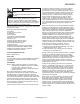
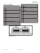
Pinout of ECU
Black Connector
Pin # Function
1 Ignition Coil #1 Ground
2 Battery Ground
3 Diagnostic Communication Line
4 Speed Sensor input
5 Fuel Injector Output #1 Ground
6 Fuel Injector Output #2 Ground
7 Oxygen Sensor Heater
8 Intake Air Temperature (IAT) sensor input
9 Fuel Pump Ground
10 Ground for IAT, TPS, MAP, O2 and Oil Sensors
11 Manifold Absolute Pressure (MAP) sensor input
12 Throttle Position Sensor (TPS) input
13 Speed Sensor Ground
14 Oil Temperature Sensor input
15 Ignition Switch (Switched +12V)
16 Power for TPS and MAP Sensors (+5V)
17 Oxygen Sensor (O2) input
18 Battery Power (Permanent +12V)
Grey Connector
Pin # Description
1 Not Used
2 Not Used
3 Malfunction Indicator Light (MIL) Ground
4 Not Used
5 Not Used
6 Not Used
7 Not Used
8 Not Used
9 Battery Ground
10 Ignition Coil #2 Ground
11 Not Used
12 Not Used
13 Not Used
14 Safety Switch Ground
15 Not Used
16 ECU
17 Fuel Pump Control (+12V)
18 Not Used
Pinout of ECU
DELPHI EFI