
User Manual


2524 690 01 Rev. D KohlerEngines.com
Tip of sensor, protruding into exhaust gas, is hollow.
Outer portion of tip is surrounded by exhaust gas, with
inner portion exposed to ambient air. When oxygen
concentration on one side of tip is different than that of
other side, a voltage signal up to 1.0 volt is generated
and sent to ECU. Voltage signal tells ECU if engine is
straying from ideal fuel mixture, and ECU then adjusts
injector pulse accordingly.
Oxygen sensor functions after being heated to a
minimum of 400°C (752°F). A heater inside sensor heats
electrode to optimum temperature in about 10 seconds.
Oxygen sensor receives ground through wire, eliminating
QHHGIRUSURSHUJURXQGLQJWKURXJKPXIÀHU,ISUREOHPV
indicate a bad oxygen sensor, check all connections and
wire harness. Oxygen sensor can also be contaminated
by leaded fuel, certain RTV and/or other silicone
compounds, fuel injector cleaners, etc. Use only those
products indicated as O2 Sensor Safe.
Manifold absolute pressure (MAP) sensor provides
immediate manifold pressure information to ECU.
MAP measures difference in pressure between outside
atmosphere and vacuum level inside intake manifold
and monitors pressure in manifold as primary means
of detecting load. Data is used to calculate air density
DQGGHWHUPLQHHQJLQHVPDVVDLUÀRZUDWHZKLFKLQ
turn determines required ideal fueling. MAP also stores
instant barometric pressure reading when key is turned
ON.
Fuel injectors mount into intake manifold, and high
pressure fuel line attaches to them at top end.
Replaceable Orings on both ends of injector prevent
external fuel leakage and also insulate it from heat and
vibration. A special clip connects each injector to high
pressure fuel line and holds it in place. Orings and
retaining clip must be replaced any time fuel injector
is separated from its normal mounting position. When
key switch is on, fuel pump module will pressurize high
pressure fuel line to 39 psi, and voltage is present at
injector. At proper instant, ECU completes ground circuit,
energizing injector. Valve needle in injector is opened
electromagnetically, and pressure in high pressure fuel
line forces fuel down through inside. Director plate at tip
of injector contains a series of calibrated openings which
directs fuel into manifold in a coneshaped spray pattern.
Injectors have sequential fueling that open and close
once every other crankshaft revolution. Amount of fuel
injected is controlled by ECU and determined by length
of time valve needle is held open, also referred to as
injection duration or pulse width. Time injector is open
(milliseconds) may vary in duration depending on speed
and load requirements of engine.
A highvoltage, solidstate, battery ignition system is
used with EFI system. ECU controls ignition output and
timing through transistorized control of primary current
delivered to coils. Based on input from crankshaft
SRVLWLRQVHQVRU(&8GHWHUPLQHVFRUUHFW¿ULQJSRLQW
for speed at which engine is running. At proper instant,
LWLQWHUUXSWVÀRZRISULPDU\FXUUHQWLQFRLOFDXVLQJ
HOHFWURPDJQHWLFÀX[¿HOGWRFROODSVH)OX[FROODSVH
induces an instantaneous high voltage in coil secondary
which is strong enough to bridge gap on spark plug.
(DFKFRLO¿UHVHYHU\RWKHUUHYROXWLRQ
EFI engines are equipped with either a 20 or 25 amp
charging system to accommodate combined electrical
GHPDQGVRILJQLWLRQV\VWHPDQGVSHFL¿FDSSOLFDWLRQ
Charging system troubleshooting information is provided
in Electrical.
An electric fuel pump module and a lift pump (two types)
are used to transfer fuel in EFI system. Three types of lift
pumps: are a pulse fuel pump, a mechanical fuel pump,
or a low pressure electric fuel pump. Pumping action
is created by either oscillation of positive and negative
pressures within crankcase through a hose, or by direct
lever/pump actuation off rocker arm movement. Pumping
action causes diaphragm on inside of pump to pull fuel
in on its downward stroke and to push it into fuel pump
module on its upward stroke. Internal check valves
prevent fuel from going backward through pump. Fuel
pump module receives fuel from lift pump, increases and
regulates pressure for fuel injectors.
Fuel pump module is rated for a minimum output of 13.5
liters per hour and regulated at 270 kilo pascals (39 psi).
When key switch is turned ON and all safety switch
requirements are met, ECU activates fuel pump module
for about six seconds, which pressurizes system for
startup. If key switch is not promptly turned to start
position, engine fails to start, or engine is stopped with
key switch ON (as in case of an accident), ECU switches
off pump preventing continued delivery of fuel. In this
situation, MIL will go on, but it will go back off after 4
cranking revolutions if system function is OK. Once
engine is running, fuel pump remains on.
Precision components inside fuel pump module are not
serviceable. DO NOT attempt to open fuel pump module.
Damage to components will result and warranty will be
void. Because fuel pump module is not serviceable,
engines are equipped with a special 10micron EFI fuel
¿OWHUWRSUHYHQWKDUPIXOFRQWDPLQDWLRQIURPHQWHULQJ
module.
,IWKHUHDUHWZR¿OWHUVLQV\VWHPRQHEHIRUHOLIWSXPS
ZLOOEHDVWDQGDUGPLFURQ¿OWHUDQGRQHDIWHUOLIW
SXPSZLOOEHVSHFLDOPLFURQ¿OWHU%HVXUHWRXVHDQ
DSSURYHGPLFURQ¿OWHUIRUUHSODFHPHQW
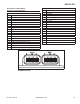
High pressure fuel line is an assembly of hoses, injector
caps and a fuel connector to fuel pump module. High
pressure fuel line feeds fuel to top of injectors through
injector caps. Caps are fastened to intake manifold and
injectors are locked into place. A small retaining clip
provides a secondary lock.
DELPHI EFI