
Technical data


2
2 - 22
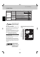
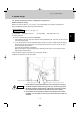
Design of Mini Multiset
DDVI 16
Use: For indoor unit (Capacity after distribution joint is 22.4 kW or less.)
Table 2-12 Dimension for Connections of Each Part
Unit: mm
210 55
145
135
185
83
103
F
HG
F
F
G
H
GH
J
J
J
F
F
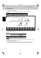
Insulator
Insulator
Gas tube Liquid tube
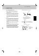
Example: (F below indicates inner diameter. below indicates outer diameter.)
F
F
H
H
H
50
I
I
I
• When creating a tube of diameter G,
use a tube cutter and cut between F
and H. Cut at a point as close to H
as possible.
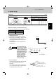
2. System Design
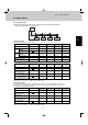
2-15. Optional Ball Valve Kit (N.A.)
Table 2-13
1. Because the diameter of this ball valve is approximately the same as the inner diameter of the connecting cop-
per tube, correction for pressure loss is not necessary.
2. Airtightness must be 3.6 MPa or more.
It is recommended that the ball valve is installed at each outdoor unit (gas tube and liquid tube), in order to
prevent refrigerant from being released into the atmosphere if the outdoor unit is eventually replaced.
NOTE
Model No.
Gas tube Liquid tube
BV-RXP160AG 15.88
BV-RXP56AG 12.7
9.52
6.35
Valve connecting tube size (mm) Indoor unit where used
16.0 kW or less
5.6 kW or less
Total capacity of indoor units
after the valve
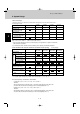
2-14. Optional Distribution Joint Kit
See the installation instructions packaged with the distribution joint kit for the installation procedure.
Table 2-11
Model name Cooling capacity after distribution Remarks
DDVI 16 22.4 kW or less For indoor unit
Position A B C D E F G H I J
Dimension –– – – –ø19.05 ø15.88 ø12.7 ø9.52 ø6.35