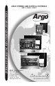
argo Hydro-Air Zoning CONTROLS INSTALLATION MANUAL AND OPERATING INSTRUCTIONS ARH-1, ARH-2, ARH-3 ARH-1 ARH-2 ARH-3 ARGO (Technical Support) 2201 Dwyer Avenue Utica, NY 13501 (Corporate Sales) 85 Middle Road Dunkirk, NY 14048 www.argocontrols.com An ISO 9001-2000 Certified Company P/N 240005131, Rev.
installation manual and operating instructions TABLE OF CONTENTS Safety Symbols...............................................................................3 Introduction......................................................................................4 Product Description.........................................................................5 Features and Benefits.....................................................................5 Control Board Diagrams...........................................
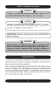
SAFETY SYMBOLS Continued ! WARNING ! Indicates a potentially hazardous situation which, if not avoided, COULD result in death or serious injury. ! CAUTION ! Indicates a potential hazardous situation which, if not avoided, MAY result in minor or moderate injury. It may also be used to alert against unsafe practices.
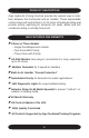
Product description Argo Hydro-Air Zoning Controls provide the easiest way to interface between the thermostat and air handler. These dependable control relays will control from 1 to 20 zones of heating/cooling and provide priority switching for domestic hot water. Boiler and A/C condenser wiring is virtually fool proof.
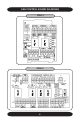
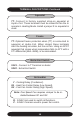
aRh control BOARD Diagrams RELAY RELAY ARh-1 6 ReLAY ReLAY ReLAY ReLAY ARh-2
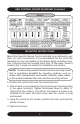
aRh control BOARD Diagrams Continued ReLAY ReLAY ReLAY ReLAY ReLAY ReLAY aRh-3 MOUNTING INSTRUCTIONS Mount the Argo ARH Series Control vertically on a solid wall or partition. For your convenience it is recommended that the control be mounted as close as possible to the device being controlled, however it should never be mounted more than 75 feet away. Select a location that is easily accessible for installation and service.
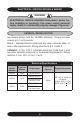
Electrical specifications & Wiring ! WARNING ! Electrical shock hazard! Disconnect power before installing or servicing. Can cause severe personal injury, death, or substantial property damage if ignored. General Wiring Notice All primary wiring must be 14 AWG minimum. Torque terminal screws 6 to 7 inch pounds. U.S.A. - National Electric Code and any other national, state, or local code requirements. Wiring must be N.E.C. Class 1. CANADA - C.S.A. C22.
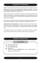
Sequence Of Operation When the thermostat calls for heat, the boiler end switch closes, starting the burner and energizing the heating circulator. The fan will operate at low speed (G1) when the water temperature is above the aquastat setting at the Hydro-Coil. When priority zone is actuated, the priority circulator and boiler end switch is energized. The heating circulator is shut off and the fan will operate at low speed (G1) until the water temperature drops below the aquastat setting.
Terminal Descriptions Continued Aquastat TT- Connect to factory supplied strap-on aquastat at Hydro-Coil. These terminals must be closed for fan the to operate in Heating Mode. Install a jumper if no aquastat is used. Freeze TT- Optional freeze protection when (TT) is connected to aquastat at Hydro-Coil. When closed, these terminals start the heating circulator, but the not fan. Using an SPST aquastat that closes when temperature falls to 40°F with a 5°F differential (MHL 480B), is recommended.
Wiring Diagram applications ARH-1 single zone hydro-air control instruction Note: Connection for 2 Speed Fan (Remove Jumper) Note: Zone 1 R & C terminals must be connected and energized for board to function.
Wiring Diagram applications ARH-2 two zone hydro-air control instruction (1 air handler and 1 priority zone) Note: Connection for 2 Speed Fan (Remove Jumper) Note: Zone 1 R & C terminals must be connected and energized for board to function. * - IF USeD. IF NOT, JUMPeR MUST Be INSTALLeD.
Wiring Diagram applications ARH-3 three zone hydro-air control instruction (2 air handlers and 1 priority zone) Note: Connection for 2 Speed Fan (Remove Jumper) Note: Zone 1 R & C terminals must be connected and energized for board to function. * - IF USeD. IF NOT, JUMPeR MUST Be INSTALLeD.
Control Expansion application Wiring Diagram for Adding ARH-1 to ARH-2 or ARH-3 RELAY RELAY RELAY RELAY RELAY RELAY 14
Replacement Parts Part Description Argo Part Number Relay 24VDC Coil R35DC Snap on Aquastat A10 18” Telephone Cable C1 Freeze Stat Aquastat A11F Technical support For technical support on this and all Argo products, please contact ECR International Technical Service at 1-800-325-5479. Please have your model number available when calling.
www.argocontrols.