argo AR SERIES CONTROLS INSTALLATION MANUAL AND OPERATING INSTRUCTIONS AR822-II, AR861-2II, AR861-3II AR861-2II AR822-II AR861-3II ARGO (Technical Support) 2201 Dwyer Avenue Utica, NY 13501 (Corporate Sales) 85 Middle Road Dunkirk, NY 14048 www.argocontrols.com An ISO 9001-2000 Certified Company P/N 240005122, Rev.
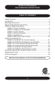
installation manual and operating instructions table of contents Safety Symbols...............................................................................4 Introduction......................................................................................5 Mounting Instructions......................................................................5 Electrical Specifications & wiring....................................................6 AR822-II Single Zone Relay AR822-II Control Features..................
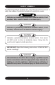
safety symbols The following defined symbols are used throughout this manual to notify the reader of potential hazards of varying risk levels. ! DANGER ! Indicates an imminently hazardous situation which, if not avoided, WILL result in death or serious injury. ! WARNING ! Indicates a potentially hazardous situation which, if not avoided, COULD result in death or serious injury. ! CAUTION ! Indicates a potential hazardous situation which, if not avoided, MAY result in minor or moderate injury.
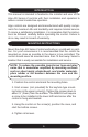
introduction This manual is intended to familiarize the installer and user of the Argo AR Series of controls with their installation and operation to assure normal trouble-free operation. Argo controls are designed and manufactured with quality components for maximum life and durability and require minimal service. To insure a satisfactory installation, it is imperative that the instructions be followed carefully before operating the control. Failure to do so may result in breach of warranty.
Electrical specifications & Wiring ! WARNING ! Electrical shock hazard! Disconnect power before installing or servicing. Can cause severe personal injury, death, or substantial property damage if ignored. – General Wiring Notice – All primary wiring must be 14 AWG minimum. Torque terminal screws 6 to 7 inch pounds. U.S.A. - National Electric Code and any other national, state, or local code requirements. Wiring must be N.E.C. Class 1. CANADA - C.S.A. C22.
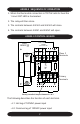
AR822-II Sequence of Operation 1. When the thermostat connection to TR/TW calls for heat the “circuit ON” LED is illuminated. 2. The relay will then close. 3. The contacts between 3/4 NO and 5/6 NO will close. 4. The contacts between 3/4NC and 5/6NC will open.
AR822-II control board • 3: Input to one pole of relay contacts • 4 NO: Normally open output, between 3 and 4 NO • 4 NC: Normally closed output, between 3 and 4 NC • 5: Input to one pole of relay contacts • 6 NO: Normally open output, between 5 and 6NO • 6 NC: Normally closed output, between 5 and 6NC T/R and T/W are the thermostat connections. When a Thermostat calls completing the circuit the relay is activated.
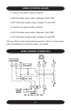
aR822-II Applications AR822-II Single Zone Application with Tankless Coil Boiler AR822-II Dual Zone Application without Tankless Coiler Boiler To Burner or Burner Control Do Not Use 9
aR822-II Applications AR822-II Indirect Tank Priority with Zone Valve Control DOMESTIC HOT WATER AR822 ARGO CIRCUIT ON T R T 24V W C NO 5 6 NC 6 + L2 L1 3 120 VAC 4 NO 4 NC JUMPER 120 VAC PRIORITY CIRC.
AR861-2II & AR861-3II control features • 2-Zone AR861-2II or 3-Zone AR861-3II • Auto-Reset Electronic Fuse Protection – Eliminates Nuisance Service Calls • 15VA Transformer – Robust Components Provide Years of Trouble -Free Service • Ice Cube Technology – Plug-In Replacement Relays • Priority Function • 5-Year Warranty AR861-2II & AR861-3II Sequence of Operation If the Priority Switch is in the “OFF” Position 1. When a zone calls for heat the corresponding zone LED is illuminated. 2.
AR861-2II control board & wiring schematic Primary Terminals 12 Relay Relay Relay Class 2 Terminals
AR861-3II control board and wiring schematic Primary Terminals 13 Relay Relay Relay Relay Class 2 Terminals
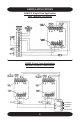
ar861-2II & AR861-3II applications Relay Relay Relay Relay The diagrams on the following pages represent the AR861-3II. The AR8612II is wired in a similar fashion. Terminals A and R Isolated End Switch Each of the low voltage controllers (SPST thermostats) will actuate a circulator and start the burner when used in conjunction with an isolated switch aquastat. Jumper: to be placed between terminals L and W . In this position A and become the isolated end switch.
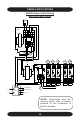
ar861-2II & AR861-3II applications T-Stat Priority T-Stat AR861-3II T1 T-Stat T2 T1 T2 T3 T3 Class 2 Wiring Primary Wiring Jumper G W L Primary Wiring A R T T GZ1 HZ1 GZ2 HZ2 GZ3 HZ3 L2 G 120 VAC L1 Hot 1 L8148 To Burner or B2 Burner Control Do Not Use C2 Priority T-Stat AR861-3II T1 Circ B1 C1 2 Circ Priority Circ T1 T-Stat T2 T2 T-Stat T3 T3 Class 2 Wiring Primary Wiring Jumper L2 G W L A R Primary Wiring GZ1 HZ1 GZ2 HZ2 GZ3 HZ3 G Priority Circ 120 VAC L
ar861-2II & AR861-3II applications ! ! WARNING Terminals W and ( W to ZC and R R Relay Relay Relay Relay AR relays will not work properly if 120 VAC polarity is not the same at the 120 VAC L and N terminals on both the AR control and the boiler aquastat. The neutral and hot wires must not be reversed. Reversing the L and N wires could result in a secondary source of power that may activate the boiler under certain circumstances that may cause serious injury or death.
Cad Cell ar861-2II & AR861-3II applications Burner L8124 A or C T T Priority T-Stat ZC T-Stat T-Stat ZR B1 AR861-3II T1 T1 T2 T2 T3 T3 Class 2 Wiring B2 C1 C2 L1 L2 Primary Wiring Jumper G W L A R L2 Primary Wiring GZ1 HZ1 GZ2 HZ2 GZ3 HZ3 Circ Circ Priority Circ G 120 VAC L1 Hot L8124 A or C T T Burner Priority T-Stat ZC T-Stat T-Stat ZR B1 AR861-3II T1 T1 T2 T2 T3 T3 Class 2 Wiring B2 C1 C2 L1 Primary Wiring Jumper L2 G W L L2 A R Primary Wiring GZ1 HZ1 GZ
ar861-2II & AR861-3II expansion technique The two controls on this page are capable of running six zones. When they are installed as shown below, only one priority and four standard zones (for a total of five zones) are available. STAT PRIORITY T1 T1 ARGO TRIPLE RELAY AR861-3 II T2 1.0 K DOMESTIC HOT WATER THERMOSTATS T2 T3 T3 1.0 K 2.7 K 15VA STAT 1.0 K 2.7 K 2.7 K Important: Both left-hand T1 terminals must be connected together and both righthand T1 terminals must be connected together.
ar series with dpm-2 outdoor reset control The DPM-2 Outdoor Reset Control is designed to raise or lower the temperature of the boiler supply water based upon a proportionate drop or rise in temperature at the outside sensor. This control plugs into Argo control equipment with a data port or as a stand alone device that can be easily wired into almost any system. See the separate DPM-2 Installation Manual for more information.
replacement parts Replacement Part Part Description Argo Part Number Replacement Control Relay R35C technical support For technical support on this and all Argo products, please contact ECR International Technical Service at 1-800-325-5479. Please have your model number available when calling. Information needed When calling model number Installation Date Installer www.argocontrols.