
Operator`s manual


56
SECTION 11
ACCESSORY INFORMATION
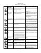
chain tensioning system and possibly, to other drive
system components. Tires should be sized this way:
a. With the tires still off the machine, inate them all
to 5.0 psi.
b. Measure the circumference of each tire using a
suitable tape measure, being sure to measure
around the center-line of the tire. Figure 11-5.
Write down the measurement on each tire. Figure
11-6.
c. Install the tires as shown in the chart (Figure
11-7).
Figure 11-5. Measuring the tire.
Figure 11-6. Marking the tire.
Two tires that measure a certain difference in circumfer-
ence when at 5 psi, will always be the same difference
in circumference when at equal pressure. Check tire
pressure every 10 hours and adjust to the pressures
shown in the chart.
Figure 11-7. Tire Sizing Chart.
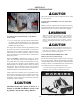
IMPORTANT
BEFORE INSTALLING THE RUBBER
TRACK SYSTEM, IT IS CRITICAL THAT
TIRE SIZING IS PERFORMED AND THE
TIRES INSTALLED AS SHOWN IN THE
CHART (Figure 11-7). PLEASE REVIEW AND
ENSURE YOU HAVE FOLLOWED THE PRE-
VIOUS INSTRUCTION BEFORE PROCEED-
ING WITH THE FOLLOWING:
8. Using a 3/4" socket, install the wheels. Use extreme care
and allow extra installation time to protect the axle exten-
sions from damage. Torque the wheel nuts to 55 ft. lbs.(75
N.m).
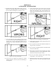
11.3.3 Standard and Super Track Installation
If the tracks, when laid on the ground, appear to curve to
one side, then turn one set so that they curve in opposite
directions, as shown in Fig. 11-8. If this is NOT done,
the vehicle may pull to the left or right during straight
line operation.