
Operator`s manual


42
SECTION 7
MAINTENANCE INFORMATION
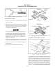
Figure 7-21. Equalizer Flat Bar.
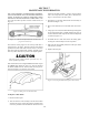
4. Adjust the cable at the transmission until the cam levers
are actually starting to pre-load the return springs and the
cam lever actuation pin on the caliper, is centered in the
"v-grove" of the cam. Figure 7-22.
Figure 7-22. Pin Centered in "V-Groove".
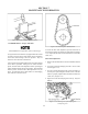
5. Locate the castle nut at the mechanical brake cam lever
and remove the cotter pin. Figure 7-23.
Figure 7-23. Castle Nut.
6. Loosen the castle nut until it can be threaded by hand.
7. Using a 0.004" feeler gauge or a piece of regular photo
copy paper (such as used for these instructions), slip it
between the emergency/parking brake pad and brake disc.
Ensure that you push the opposite side pad up against the
brake disc before setting this gap.
8. Slowly hand tighten the castle nut until the feeler gauge
(or piece of paper), becomes snug between the pad and
brake disc.
9. Back off the castle just enough for a new cotter pin to be
installed. The feeler gauge (or piece of paper), should pull
out at this point with just the slightest bit of resistance.
10. Lock down jam nuts at the parking brake adjustment
bracket on the transmission.
11. Check to ensure that the brakes are NOT engaged when
the Brake Lever is in the down & off position.
12. Check for drag by driving without activating any brakes
for about 100 feet. Stop and check for heat on the brake
discs. They should both be cool (or no hotter than the
beginning of the test). Adjust if necessary.
13. Check the effectiveness of the parking brake by parking
the Argo on the steepest hill encountered and by loading
to it’s maximum working load. The parking brake should
hold the Argo from moving.
14. Check the effectiveness of the emergency brake by ac-
tivating it while coasting down a slight grade. The Argo
should come to a controlled stop without pulling left or
right. Re-adjust the brakes if necessary.