
Operator`s manual


37
SECTION 7
MAINTENANCE INFORMATION
IMPORTANT
It is ultimately the responsibility of the operator to determine
a SAFE MAXIMUM load capacity in accordance with
the driving terrain, conditions and vehicle specications.
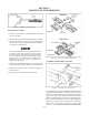
7.2.7 TIRE REPAIR AND REPLACEMENT
Repair a at tire by removing the tire completely from the
rim. Proper tire changing equipment is necessary to remove
and remount the tire. Your authorized ARGO dealer will have
the necessary tools.
Apply a radial tire patch on the inside of the tire over the
puncture or hole.
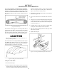
Remount the tire on the rim using a bead lubricant such as
Murphy's Tire & Tube Mounting Compound. Spoon the tire
onto the rim to prevent tire bead area damage. THE TIRE
MAY EXPLODE IF OVER-INFLATED. Place the tire and
rim assembly in a protective cage to inate and to seat the
beads. Never inate over 32 psi (220 kPa) to seat the bead.
Once both beads are seated, deate to 2.5 to 3.5 psi (17 to 24
kPa), 7 psi (48 kPa) maximum operating pressure. A special,
low pressure tire gauge (ARGO Part No. 619-10) is available
from your ARGO dealer.
Replace badly worn or damaged tires with original equip-
ment Argo tires. Consult your ARGO dealer if in doubt. Any
other tires (size, type or tread pattern), will affect the skid
steering characteristics of the vehicle and may cause vehicle
damage.
ARGO track systems are designed for use ONLY with original
equipment Goodyear, Carlisle or ARGO tires.
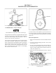
7.2.8 AXLE BEARING MOUNTING
The axles are mounted to the Argo using special cork gas-
kets between the anged bearings and the outside surface of
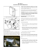
the lower body (see Figure 7-15). During the initial run-in
period, the gasket material may relax causing the nuts to
loosen slightly. These should be checked and re-tightened
after initial 8 hours of use and then after every 100 hours.
See Figure 7-16.
Figure 7-15. Bearing Flange and Cork Gasket
Figure 7-16. Re-tightening bolts.
7.3 HYDRAULIC BRAKES
7.3.1 GENERAL
Although the hydraulic brake system is self adjusting, the
following require periodic attention:
7.3.2 BRAKE FLUID LEVEL
After every 50 hours of operation, check the brake uid level
by removing the master cylinder covers.
IMPORTANT
Thoroughly clean the master cylinder cover and surround-
ing area before removal.
The master cylinders are mounted tilted slightly back. When
adding uid, ll until the shallowest end of the uid level in
the well is approximately 1/2" from the top lip of the master
cylinder (Figure 7-17).