
Operator`s manual


36
can be ordered from your ARGO dealer (ARGO Part No. 658-
08) or refer to Appendix 1 for modication information.
3. Replace the outside plate and spring clip as shown in Figure
7-5. Note: Avenger and Frontier models are secured with
two (2) cotter pins. Always use new cotter pins.
4. Repeat steps 1 to 3 to replace the other idler chain.
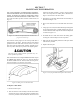
7.2.6 TIRE INFLATION
Improperly inated tires can cause the vehicle to pull to
one side, requiring constant steering correction. Suggested
ination for the Argo 25x12.00-9, Argo 24x10.00-8, Argo
22x10.00-8 and Argo HEAT 25x12.00-9 is between 2.5 to
3.5 psi (17 to 24 kPa). Maximum operating pressure is 7 psi
(48 kPa).
A special low pressure tire gauge (ARGO Part No. 619-10) is
available from your ARGO dealer.
CHANGING TIRE PRESSURE FOR DIFFERENT
TERRAIN CONDITIONS
The tire pressure should be adjusted between 2.0 and 7.0 psi
according to differences in terrain. Observance of these guide-
lines will lead to less wear & tear on both vehicle and tires.
The operator should equip the vehicle with a low pressure tire
gauge (Part No. 619-10) and with a hand pump.
RECOMMENDED GUIDELINES for TERRAIN
Soft Ground:
Low Pressure • On soft terrain, use lower pressure.
Hard Ground:
Higher Pressure • On hard terrain and water, use higher
pressure.
Rocky Ground:
Highest Pressure • On rough or rocky terrain, ll to, but
not more than the recommended
range indicated on the tire sidewall.
This will reduce the possibility of tires and rims being dam-
aged during heavy duty applications.
It is also important to observe the recommended load capaci-
ties of your vehicle when travelling on different kinds of ter-
rain. For load capacities of your particular vehicle, see Section
1 of General Information in this operators guide.
SECTION 7
MAINTENANCE INFORMATION
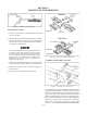
To Remove the Idler Chains:
Loosen the power pack clamping nuts and adjusting bolts as
shown in Figure 7-13 and proceed as follows:
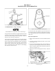
1. Place the gearshift in neutral and roll the vehicle until the
connecting link of one of the idler chains is positioned as
shown in Figure 7-14.
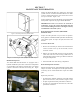
2. Remove the spring clip or cotter pins, depending on model,
from the connecting link. Remove the outside plate and tap
out the connecting link. On models that utilize a double
40 or 50 drive chain, as the connecting link is removed, the
inside plates will be released (refer to Figure 7-6). Models
with single 60 drive idler chains have no inside plates.
3. Remove the idler chain from the vehicle.
4. Repeat steps 1 to 3 to remove the other idler chain.
Do not over tighten idler chains. Premature chain
wear, bearing wear or idler shaft failure can occur.
Figure 7-14. Position of idler chain link for removal.
To Install the Idler Chains:
1. Install the chain over the brake disc sprocket and the idler
shaft sprocket.
2. Pull the ends of the chains together and insert the connect-
ing link. Insert the inside plates before pushing the con-
necting link into position (double 40 or 50 chain models
only).
NOTE: Use a pair of modied 7R Vice Grips to hold the ends
of the chain together while inserting the connecting link. There
may be no slack in the idler chain, making installation of the
connecting link difcult without this tool. Modied Vice Grips