
Operator`s manual


33
SECTION 7
MAINTENANCE INFORMATION
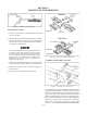
Figure 7-5. Removal of the spring clip.
To install the Drive Chains:
1. Position the drive chain over the slider block and around
the drive sprockets.
2. Pull the ends of the chain together and insert the connecting
link as shown in Figure 7-6 and 7-7. When connecting the
RC50-2 chain, insert the inside plates before tapping the
connecting link into position.
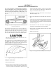
Use a pair of modied 7R Vice Grips to hold the ends of
the chain together while inserting the connecting link.
Some drive chains have no slack, and replacement of
the connecting link is difcult without this tool. Modi-
ed Vice Grips can be ordered from your ARGO dealer
(ARGO Part No. 658-08) or refer to Appendix 1 for
modication information.
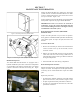
3. Replace the outside plate and spring clip. The open end of
the clip must face rearward when it is on top of the chain.
4. Remove the vice-grips securing the cam assembly in its
lowest position.
5. Repeat steps 1 to 4 until all chains are replaced.
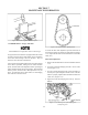
Figure 7-6. Chain connection link components.
7.2.4 DRIVE CHAIN TAKE-UP SYSTEM
Figure 7-7. Installing the connecting link
The chain tensioning system on all models consists of a torsion
spring loaded cam assembly with a slider block which takes
up the slack on the bottom side of all but the front nal drive
chains. As the chain wears, the chain tensioning mechanism
adjusts semi-automatically. Under most conditions, the ten-
sioner cam assembly will move to the next step of adjustment
simply due to normal drive system dynamics. Sometimes,
however, the cam assembly can bind due to debris caught
in the area. IT IS VERY IMPORTANT TO CHECK THAT