
Operator`s manual


31
SECTION 7
MAINTENANCE INFORMATION
• cracks, fraying or shredding is apparent
• it becomes contaminated with oil or some other uid
Refer to the ARGO Parts Manual for correct drive belt part
number.
Drive Belt Adjustment
To extend the life of the drive belt, the INVANCE driven
clutch allows for some adjustment to reset the belt height if
necessary. If belt wear causes the belt to start sitting below
the sheaves at idle, adjustment can be made to bring the belt
back up to ush or 1/10" above the sheaves.
1. Remove the driven clutch from the vehicle and move to
a clean work bench.
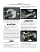
2. Loosen both jam nuts located on the xed face of the
clutch. Figure 7-2a.
Figure 7-2a. Loosen jam nuts.
3. Using an allen wrench, turn the adjustment set screw
either in (to lower the belt) or out (to raise the belt) be-
tween the clutch sheaves. Figure 7-2b.
IMPORTANT
Loosen set screws uniformly 1/2 turn at a time. It is
crucial that the clutch faces remain true and parallel to
each other around the entire circumference of the sheaves.
4. After adjustment, check belt level by placing a drive
belt between the sheaves. Belt position should be
anywhere from ush with the top of the sheaves, to
1/10" above. Re-tighten jam nuts and torque to 60-75 in.
lbs. (7.5 +/- 1 Nm)
Figure 7-2b. Turn the adjustment set screw.
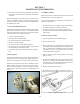
To Remove the Drive Belt
The Invance Driven Clutch (transmission clutch), is
manufactured with a 6mm x 1.0 threaded hole in the clutch
face. This hole is provided to assist in spreading the driven
clutch pulleys apart by threading a 6mm x 1.0 thread bolt
in through the face. This bolt should be a least 2” in length
with full thread. Spreading the pulleys allows for easy
removal and installation of the 127-137 (Avenger) or 127-159
(Frontier) drive belt. Figure 7-2c.
Figure 7-2c. Drive belt removal.
To install the Drive Belt:
If this procedure is not carried out as described, the edge
of the xed face may cut or damage the drive belt.
1. Position the belt around the driver clutch rst.