RTrak-HAB Integrated High Altitude Balloon APRS Tracker/Telemetry Payload User’s Manual Revision A Written By: Jason Rausch KE4'YV Copyright 2011 RPC Electronics, LLC
Table of Contents 1. 2. 3. 4. 5. 6. Introduction and Acknowledgments Package Contents Device Overview and Specifications Connections Getting Started Basic APRS Programming • Callsign • Icon • APRS Path • Beacon Rate 7. Telemetry/Control Header 8. Dual-Frequency Operation 9.
Introduction Thank you for purchasing an RTrak-HAB! We are pleased that you have decided to make it part of your amateur radio equipment and hope that it will serve you well for many years to come. Please take some time to read through this manual and familiarize yourself with the functions of your new RTrak-HAB and how to operate it properly.
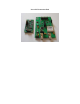
Package Contents • Your new RTrak-HAB comes with everything required to get started.
Device Overview and Specifications • The RTrak-HAB is the first APRS tracker designed specifically for the high altitude balloon community. We have worked closely with HAB enthusiasts to include all of the features needed for a truly versatile payload. OpenTracker 1+: The data modem section of the RTrak-HAB is based on the SMT OpenTracker 1+ platform. The OpenTracker was designed and programmed by Scott Miller N1VG of Argent Data Systems.
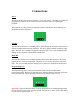
Connections Power The RTrak-HAB can be powered with any 5.5-12 VDC source. The LDO (Low Dropout Regulators) used allow for the tracker to be powered from battery for lightweight payloads. The connector is a three position solder pad connector suitable for direct soldering or a pin header for quick disconnect. GPS RF The GPS RF connection is a standard polarity, SMA female RF connector suited to mate with the included GPS active patch antenna. Be sure to tighten antenna connector finger tight.
Power/RF Connection End
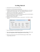
Getting Started • Getting started is easy with the RTrak-HAB. 1. Connect power, VHF antenna and GPS antenna. 2. Install the programming software included on the RTrak-HAB User’s CD on any 3. 4. 5. 6. computer with a 9 pin serial port. Note: Some USB>Serial adapters have been reported to work with this software. Use at your own risk. Ensure that power to RTrak-HAB is REMOVED. Remove the jumper block and connect the programming cable to the RTrak-HAB’s programming port and the computer’s serial port.
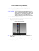
Basic APRS Programming • Callsign: Use your FCC assigned Amateur Radio callsign for this field Examples: KE4NYV KI4UDD N1VG • Callsign with SSID: The use of an SSID can aid in the multiple use of a single callsign. The SSID ID will be designated by a dash (-) sign and a number of 1-15. These SSIDs typically have specific meaning, so check with your local APRS users for the SSID that is appropriate for a non-receiving APRS tracker.
Beacon Rates: The RTrak-HAB is capable of two beacon schemes. 1. Static Beacon – This method uses a pure timing scheme to beacon at a constant rate set in programming. This rate cannot be changed unless the configuration software and cable are used to make the change. The static beacon rate is set in seconds, meaning 30 = 30 seconds, 60 = 1 minute and so on. A typical static beacon rate is 3-5 minutes. 2. SmartBeaconing™ – This method uses the current GPS data to determine when to beacon and how often.
Default Programming Window
Telemetry/Control Header • The RTrak-HAB employs a full telemetry and controls package as part of the tracker payload. All ADC raw values are reported in the payload of the APRS packet. • The ADC (Analog to Digital Converter) channels can accept any analog voltage between 0-5VDC. These channels have on-board 3.3K pull-up resistors and 0.1uF decoupling capacitors. The GPO (General Purpose Output) channels can control numerous devices during flight. GPO 0-2 switches ground.
Dual-Frequency Operation • The RTrak-HAB is capable of operating on two independent VHF frequencies when in flight. This is accomplished by editing the frequency information in the configuration software. 1. The first step is to read the tracker’s current programmed profile with the configuration software. 2. Next, click on the “Freq” button to open up the editing window.
3. The frequency editor window will open up and have defaults loaded in the slots. 4. There are eight total frequency slots provided, but only two can be used at any given time. Normally, this would be slot 1 and slot 2. Use the selection dots (also known as “radio buttons”) to assign a frequency slot to the primary and secondary channels. Primary Channel is the default frequency used on power up and is controlled by the beaconing timing/scheme selected on the primary configuration window.
Major Component Specifications • • • OpenTracker 1+ • Operating Voltage • Operating Current • Modes • Format • GPS Interface 5VDC Regulated 8 mA Idle, 20 mA Transmitting 1200 bps AFSK APRS Standard NMEA 4800 bps Trimble Compernicus GPS • Receiver Class • Channel • Operating Voltage • Cold Start Lock Time • Interface • Sensitivity • Maximum Altitude • Operating Current Sirf-Star III 20 3.25-3.