RTrak-Lite Integrated APRS Tracker User’s Manual Revision A Written By: Jason Rausch KE4%YV Copyright 2011 RPC Electronics, LLC
Table of Contents 1. 2. 3. 4. 5. 6. Introduction and Acknowledgments Package Contents Device Overview and Specifications Connections Getting Started Basic APRS Programming • Callsign • Icon • APRS Path • Beacon Rate 7.
Introduction Thank you for purchasing an RTrak-Lite! We are pleased that you have decided to make it part of your amateur radio equipment and hope that it will serve you well for many years to come. Please take some time to read through this manual and familiarize yourself with the functions of your new RTrak-Lite and how to operate it properly.
Package Contents • Your new RTrak-Lite comes with everything required to get started, minus the radio, antenna and computer for initial programming. Included Items: • RTrak-Lite APRS Tracker • Active GPS Patch Antenna • 12VDC Lighter Power Cable • DB9 Serial to 2.
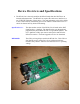
Device Overview and Specifications • The RTrak-Lite is the only model in the RTrak family that does NOT have an internal radio/transmitter. The RTrak-Lite requires the end user to interface it to any VHF/UHF FM radio of their choice. The main advantage to this is the ability to use a radio with any transmitting power level and have an internal receiver to check for channel activity before transmitting. OpenTracker 1+: The data modem section of the RTrak-Lite is based on the SMT OpenTracker 1+ platform.
Connections • There are three main connections that will be used any time the RTrak-Lite is in full operating mode: Power, GPS Antenna and Radio. Power The RTrak-Lite can be powered with any 9-20 VDC source. This makes it perfect for use in a vehicle, boat or just about any other mobile form of transportation. The power jack is a standard coaxial 2.1mm I.D. jack with a positive center (tip) polarity The included lighter cable is perfect for most vehicle applications.
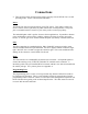
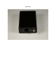
Rear Panel
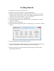
Getting Started • Getting started is easy with the RTrak-Lite. 1. Simply connect the included power cable and GPS antenna. 2. Install the programming software included on the RTrak-Lite User’s CD on any 3. 4. 5. 6. computer with a 9 pin serial port. Note: Some USB>Serial adapters have been reported to work with this software. Use at your own risk. Ensure that power to RTrak-Lite is REMOVED. Connect the programming cable to the RTrak-Lite’s programming port and the computer’s serial port.
Basic APRS Programming • Callsign: Use your FCC assigned Amateur Radio callsign for this field Examples: KE4NYV KI4UDD N1VG • Callsign with SSID: The use of an SSID can aid in the multiple use of a single callsign. The SSID ID will be designated by a dash (-) sign and a number of 1-15. These SSIDs typically have specific meaning, so check with your local APRS users for the SSID that is appropriate for a non-receiving APRS tracker.
• Beacon Rates: The RTrak-Lite is capable of two beacon schemes. 1. Static Beacon – This method uses a pure timing scheme to beacon at a constant rate set in programming. This rate cannot be changed unless the configuration software and cable are used to make the change. The static beacon rate is set in seconds, meaning 30 = 30 seconds, 60 = 1 minute and so on. A typical static beacon rate is 3-5 minutes. 2. SmartBeaconing™ – This method uses the current GPS data to determine when to beacon and how often.
Major Component Specifications • • OpenTracker 1+ • Operating Voltage • Operating Current • Modes • GPS Interface DC 6.5-28V or 5VDC Regulated 8 mA Idle, 20 mA Transmitting 1200 bps AFSK NMEA 4800 bps M%5010HS • Receiver Class • Channel • Operating Voltage • Cold Start Lock Time • Interface • Sensitivity • Maximum Altitude • Operating Current Sirf-Star III 20 3.25-5.
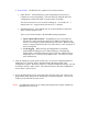
Appendix A • Radio Port Pinout • When using the supplied interface cable, the color code in the above table will be valid. If using an aftermarket cable or hand made cable, verify color code before using! If you are powering the RTrak-Lite via the 2.1mm coaxial power jack, the only required pins of the radio port are: 1, 3, 5 and 6.