Argent Data Systems OpenTracker USB User’s Manual Revised 2-25-2013 Argent Data Systems, Inc. PO Box 579 Santa Maria, CA 93456-0579 USA (800) 274-4076 / +1 805 619-4515 Fax (866) 302-6890 www.argentdata.
OpenTracker USB User’s Manual 1. 2. 3. Introduction .............................................................................................................. 1 Major Features .......................................................................................................... 1 Hardware Description............................................................................................. 3 3.1. SERIAL Connector Pin Assignments ............................................................ 3 3.2.
OpenTracker USB User’s Manual 1 1. Introduction The OpenTracker USB was designed as a low-cost entry-level APRS tracker, but it includes features previously found only on significantly more expensive models. The OpenTracker USB includes almost all of the features of the higher-end Tracker2, with the exception of the digipeater and Garmin protocol functions. Firmware updates and enhancements are published frequently, so check our website at http://www.argentdata.
OpenTracker USB User’s Manual Telemetry – The OpenTracker USB has on-board temperature and voltage sensors, plus four analog 0-20v inputs and two digital input/output pins. Temperature and voltage readings can be reported in status packets, and the other readings can be reported in an APRS telemetry message. Scripting – To automate a variety of tasks and increase the device’s feature set, the OpenTracker USB includes a simple user-programmable script system.
OpenTracker USB User’s Manual 3. Hardware Description 3.1. 2: 3: 4: 5: 7: 8: SERIAL Connector Pin Assignments Data in (port A) Data out (port A) Power output for GPS Ground Data out (port B) Data in (port B) Note: The serial interface is configured as DTE (data terminal equipment) to allow direct connection to a GPS receiver. Connection to a PC requires a nullmodem cable. 3.2. 1: 2: 3: 5: 6: 7: 8: 9: 3.3.
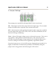
OpenTracker USB User’s Manual 4 4. Jumper Settings Three settings are controlled by the jumper block on the circuit board. ‘HI’ – This jumper sets the audio output level to the high range. This is needed mostly for mobile radios, especially some commercial models. ‘HT’ – Selects if push-to-talk signaling through the audio output line is enabled. Use this jumper with most HTs by Icom, Yaesu, and Alinco handhelds, but not Kenwood, Puxing, and Baofeng.
OpenTracker USB User’s Manual 5 5. Setup and Configuration You can use a PC to connect to the OpenTracker USB using either the Windows configuration program (otwincfg.exe) or a terminal emulation program of your choice, such as HyperTerminal, PuTTY, or Minicom. Either the serial port or the USB port may be used for configuration. To use the command console, connect at the proper baud rate (4800 baud is the default) and press enter several times until you see a command prompt.
OpenTracker USB User’s Manual 6 Mac OS X should assign a device name starting with /dev/cu.usbmodem. Other modern operating systems should be able to use the OpenTracker USB as a generic CDC ACM serial device. Its VID is 0x134A and PID is 0x9000. 6. Position Modes Before getting started, it’s important to understand that the tracker ordinarily will not make automatic transmissions (including position, status, weather, and telemetry packets) unless it knows where it is.
OpenTracker USB User’s Manual 7 KISS – In KISS mode, a PC or other host device sends and receives raw AX.25 packets. Keep in mind that even with one or both ports in KISS mode, the tracker will continue to perform its other functions, including messaging and remote command access. The host should use a different callsign/SSID combination to avoid interference. WS2300 – Supports LaCrosse WS-2300 series weather stations at 2400 baud, again ignoring manual baud rate settings.
OpenTracker USB User’s Manual 8 8. Remote Access Commands can be issued to the tracker remotely via APRS messages. The originating station’s callsign must appear in the device’s security authorization list (see AUTHLIST command.) Commands are prefixed with ‘CMD’, and the results of the command, if any, will be send back as an APRS message to the sending station. For example, ‘CMD VERSION’, sent from an APRS client, will cause the target device to reply with its firmware version.
OpenTracker USB User’s Manual 9 exit safe mode, use the RESET command or power off the tracker after removing the jumper used to enter safe mode. The use of the default configuration is temporary. Normal operation will be resumed when safe mode is exited. To overwrite the active configuration with the saved defaults, use the RESET DEFAULT command. The tracker need not be in safe mode to restore defaults.
OpenTracker USB User’s Manual 10 10. Authentication In addition to the security authorization list, remote access to the tracker can be controlled through a more secure one-time password mechanism. This mechanism is enabled by setting PWAUTH ON. To set up one-time password authentication, use the command SECRET followed by a pass phrase of at least 16 characters. The device will use this pass phrase to generate a 128-bit key that is stored in nonvolatile memory.
OpenTracker USB User’s Manual 11 11. OTWINCFG Configuration Program The OpenTracker USB can be configured using the otwincfg.exe program under Windows. The program is available for download at http://www.argentdata.com/support. Connect the tracker and start the configuration program. The first window displayed allows you to select the COM port that the tracker is connected to. 11.1.
OpenTracker USB User’s Manual 11.4. 12 Warm Boot vs. Cold Boot If the unit is already powered on and operating when you click the ‘Connect’ button, the program attempts a ‘warm boot’ operation to put the device into configuration mode. If the firmware has been corrupted, i.e. by a failed upgrade, it may fail to enter configuration mode. You can correct this by performing a ‘cold boot’ - power the unit off and power it on again after clicking ‘Connect’. 11.5.
OpenTracker USB User’s Manual 11.7. 13 Configuration Profiles The OpenTracker USB can store two separate configuration profiles. The profile currently being shown is selected using the tabs at the top of the window labeled ‘Profile 1’ and ‘Profile 2’. When it is first powered on, the tracker will always start out using Profile 1. After startup, profile selection depends on the settings in the profile switching screen. To access these settings, click ‘Profile Switching’.
OpenTracker USB User’s Manual 14 Symbol Table and Symbol Code – These settings control the symbol used to indicate the station’s position when drawn on a map. See Appendix B for a listing of available symbols. Temp. Adjust – Calibration offset for onboard temperature sensor. The sensor used on the OpenTracker is fairly linear across its operating range and requires a single-point calibration. The easiest way to accomplish this is to set a thermometer next to the tracker.
OpenTracker USB User’s Manual 15 Voltage – Report input voltage in the comment field. The maximum value is 18.5 volts, and the minimum is the dropout voltage of the regulator – typically 6.7 volts. Compressed – Enables Base91 compressed position reporting. This mode is widely, but not universally, supported. Packets in Base91 format are shorter than their uncompressed equivalents and provide greater position resolution. Telemetry every n – Sends a telemetry packet every n transmissions.
OpenTracker USB User’s Manual 16 Use PTT Input – When this checkbox is enabled, the tracker can be connected inline with a microphone to operate in burst-after-voice (mic encoder) mode. A packet will be transmitted whenever the microphone PTT is released. Timeslot – The timeslot option is typically used to coordinate multiple trackers, especially for special events where many transmitters will be sharing the same channel with a high beacon rate.
OpenTracker USB User’s Manual 17 Save – When enabled, the tracker will save its last-known GPS position as a permanent fixed position if the GPS fix is lost. This may be used in the case of a temporary weather station where a GPS receiver is installed only during setup and is removed to conserve power. The system must remain powered on for 30 seconds after GPS fix loss before the position is saved.
OpenTracker USB User’s Manual 18 Debounce – This is a delay applied to the counter input. After a counter event is registered, all subsequent events are ignored until the specified time has elapsed. Without a suitable debounce setting, a typical pushbutton could register several events for one press. Power Control – When selected, the tracker will activate its power control line (AUX IO) before each transmission.
OpenTracker USB User’s Manual 19 No Suppress PTT Out on PTT In – This option allows the tracker to be used in burst-after-voice mode without breaking any lines between the microphone and radio. PTT is not asserted by the tracker until the microphone PTT is released. External Squelch – Enables the use of an external squelch or COR input. Copy from Profile n – This button copies the contents of one profile to the other. 11.10.
OpenTracker USB User’s Manual 20 11.11. Access List This screen allows editing of the tracker’s remote access control list. 11.12. Profile Switching To access the profile switching setup, click on the ‘Profile Switching’ button from the main configuration screen. The conditions to test are selected using the checkboxes to the left of each condition.
OpenTracker USB User’s Manual 21 equal to). Clicking on the button showing the comparison operator toggles it between these two settings. The Altitude and Speed values are compared with those indicated by the GPS. Onboard sensors provide readings for comparison with the Temperature and Voltage fields. ADC Input refers to the extra unused analog-to-digital converter input on X1 pin 9. The possible values are 0 to 255, corresponding to a range of 0 to 20 volts.
OpenTracker USB User’s Manual 22 12. Command Reference Most commands can be issued through the serial console, APRS message, or fleet management message. Some commands make sense only when used from the local console and are not available for remote access. The OpenTracker USB will accept command abbreviations. A minimum of three characters must be entered. For example, CALIBRATE can be entered as CAL.
OpenTracker USB User’s Manual 23 AUTHLIST +/- Displays or changes the list of callsigns authorized for remote access. +callsign adds a callsign to the list, -callsign removes a callsign from the list, and 'none' erases the entire list. Up to six callsigns can be stored. AUTOBAUD on|off Enables automatic baud rate detection. When a baud rate mismatch is detected, the unit will attempt to automatically select the proper baud rate.
OpenTracker USB User’s Manual 24 CDINVERT on|off Inverts carrier detect input polarity. CNTRESET on|off Causes counter to reset with each transmission. See accessory port information. COMMENT Sets beacon text / comment string, up to 64 characters. COMPRESS on|off Enables Base91 compressed format for position transmissions. CONFIG 1|2 Selects configuration profile to modify.
OpenTracker USB User’s Manual Return value: Number of devices detected DISPLAY Lists all configuration parameters. 25 (local only) DOUBLE on|off When enabled, two identical copies of the position packet are sent with each transmission. This should only be used with short packets when extra redundancy is required. DUMP (local only) Displays the tracker’s memory contents for troubleshooting purposes. By default only RAM contents are displayed.
OpenTracker USB User’s Manual 26 GPIO on | off | toggle | in Reads or sets state of a general-purpose digital I/O pin. ‘On’ sets the pin to the high state, ‘Off’ sets it to low state, ‘Toggle’ reverses the state of the pin, and ‘In’ switches the pin to input mode and returns 1 or 0 depending on the input signal. This command is used primarily for scripting. Pin output state settings are not retained when power is lost. See the telemetry section of this manual for details on pin assignments.
OpenTracker USB User’s Manual 27 MYCALL Sets the unit's callsign and optional SSID. NICE When the tracker hears one of its own packets digipeated, it will skip the following transmissions. This allows a faster beacon rate to be used in areas with poor coverage, without increasing the load on the network in areas with better coverage. OUTPUT1 on|off Not currently implemented. PASSALL on|off Normally the tracker ignores all received packets that fail a frame check sequence test.
OpenTracker USB User’s Manual 28 POWER on|off|<0-255> (seconds) ON or OFF will manually set the state of the power relay control pin (AUX IO). Specifying a value in seconds will enable automatic power control mode, where the power output is turned on for the specified number of seconds prior to transmission, and turned off immediately after transmission. Return value: 0 = Off, 1 = On, 2 = Timed PROFILE 1 | 2 Selects the configuration profile to use. PROPWPT on|off Enables proprietary waypoint strings.
OpenTracker USB User’s Manual 29 RETRYTIME <0-255> (seconds) Time between message retry attempts - interval increases by this value with each transmission. REQALL on|off Require all configuration switch parameters to be met before switching profiles. RESET Perform software reset. Saved settings are unaffected. RING on|off Sends a bell character whenever an incoming message arrives. SCRIPT on|off Enables the script engine.
OpenTracker USB User’s Manual 30 Between these two extremes, the interval varies between the low rate and high rate (specified separately with the INTERVAL command) depending on the speed. The and settings define these two limits. For storage efficiency, the speeds are represented in units of 32 centimeters/second. To convert from miles per hour, multiply by 1.397. To convert from kilometers per hour, divide by 1.152. Setting MPH Km/h 5 3.6 5.7 10 7.2 11.5 15 10.
OpenTracker USB User’s Manual 31 STATUS <0-255> Status packets are sent every n transmissions, or if set to 0, status text is sent as part of the position packet. SYMBOL <1-2 characters> APRS symbol character, optionally preceded by symbol table or overlay identifier. TELEMETRY on|off Enables transmission of telemetry packets. TEMP on|off Enables transmission of temperature readings from the on-board temperature sensor. TEMPADJ <-128 to 127> (degrees C) Offset for temperature sensor in degrees C.
OpenTracker USB User’s Manual 32 TXLEVEL <1-255> Sets transmission audio level. This value should be selected to provide an appropriate FM deviation level, typically about 3.5 kHz. TXNOFIX on|off Allows transmission of last position if GPS fix is lost for more than 30 seconds. Default behavior is to cease transmitting the position in the absence of a valid GPS signal. TXONCHG on|off Causes an immediate transmission when switching configuration profiles.
OpenTracker USB User’s Manual 33 13. Telemetry The OpenTracker USB has the ability to send telemetry information from its onboard temperature and voltage sensors, and header CN4 provides four 0 to 20 volt analog inputs and one general-purpose digital input/output pin. When telemetry reporting is enabled, the tracker transmits standard APRS telemetry reports in the following format: T#sss,aaa,bbb,ccc,ddd,eee,76543210 The ‘sss’ field is a sequence number that increments with each report.
OpenTracker USB User’s Manual 34 14. Script System The OpenTracker USB’s script engine allows simple programs to be run on the tracker to customize the tracker’s operation and automate tasks. Use the ‘script’ button in the otwincfg utility to access the script editors. Common script tasks include handling multiple beacon texts, responding to events such as door alarms or high temperatures, transmitting APRS objects or telemetry parameters, and changing regional settings automatically.
OpenTracker USB User’s Manual 35 The highlighted line in the script listing shows where the next command will be inserted. The 'Delete Line' button deletes the currently selected line, and the 'Up' and 'Down' buttons move the line in the listing. Conditional commands cause automatic indentation in the listing. The numbers directly under the listing show the amount of script memory used. Commands that accept one or more parameters use the values in the A, B, C, T, X, Y, area corners, and flags fields.
OpenTracker USB User’s Manual 36 To compare the current altitude to a fixed value, for example, you can select "Altitude" in box A and enter "10000" in box C, and click the "If A > C" button to create the line "If Altitude > 10000". The next command entered will be indented, indicating that it will only be executed if that condition is true. The "End Block" command ends the conditional statement. "Else" reverses the sense of the last conditional statement and should be used before the closing "End Block".
OpenTracker USB User’s Manual 37 On Startup Executes a block of code only once, immediately after the tracker is powered on. On Second Executes a block of code once per second. On Interrupt Executes a block of code whenever a low-going edge is detected on the CT (counter/trigger) pin. On GPS Fix Executes the following block whenever a valid GPS position fix is obtained. Set A = B Sets a counter to the value in another counter. Set A = C Sets a counter to the value specified in box C.
OpenTracker USB User’s Manual 38 Use this command carefully - the tracker's flash memory has a write endurance of about 100,000 cycles, and any command that changes a value in the tracker's configuration will require a flash write. At 8 script executions per second, an errant script could wear out the flash memory in a few hours. Flash writes also cause the received packet buffer to be discarded. Use flags or ‘Do Once’ to avoid executing the same command repeatedly.
OpenTracker USB User’s Manual 39 These general-purpose counters have no predefined meaning, and they have no effect on the rest of the system. Ticks This counter increments every 1/1200 second, and counts from 0 to 1199. TX Counter Seconds elapsed since the last automatic transmission. Second This counter indicates the second of the current hour (synchronized to GPS time) from 0 to 3599. Pulse Count This counter is used by the event counter function described elsewhere in this manual.
OpenTracker USB User’s Manual 40 15. UI-View32 Setup For use with the UI-View32 APRS client, either port of the tracker can be set manually to KISS mode. No configuration commands are needed in UI-View32 once this has been accomplished. In this example, port A has been set to KISS mode at 9600 baud using the tracker configuration utility. The console commands AMODE KISS and ABAUD 9600 produce the same result.
OpenTracker USB User’s Manual 41 No ‘Into KISS’ or ‘Exit KISS’ commands are needed, and any settings in these fields should be deleted. Placing a ‘0’ in the ‘Exit KISS’ field avoids a bug in UI-View32 that prevents it from exiting properly when the option is left blank.