
User`s manual

Tracker3 User’s Manual 11
8. Hardware Description – T3-135
The Tracker3 model T3-135 is a plug-in board for the Alinco DR-135T. It can also
be used with the DR-235 and DR-435 models.
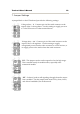
To install the board, disconnect power to the radio and remove the four screws
holding on the bottom cover plate. A multi-colored cable connects the rear
connector to the radio’s main board. Remove the cable from the radio board,
plug it in to the receptacle on the T3-135 board, and plug the T3-135 board’s cable
into the radio board. The supplied hook and loop fastener can be used to secure
the T3-135 board to the VCO case.
A short USB pigtail cable is also provided with the board. The small end plugs
in to the T3-135 board, and the cable can be routed out of the radio by bending or
cutting the metal tab on the radio’s cover that covers the space above the speaker
jack.
The T3-135 board is active only when the radio is placed in digital mode,
indicated by a square wave icon on the display. When the radio is tuned to a
memory channel that has the digital option set, the tracker will power up
automatically. The tracker must be powered up before it can be configured.
In data mode, the front-panel ‘Data’ jack is used as the tracker’s port B input,
with data in on the tip, +5v power out on the ring, and ground on the sleeve.
This input can be used for weather station or NMEA GPS input. Be sure to check
the polarity of the power output before using it the first time – some earlier DR-
135T radios may have an inverted output. If a complete reset of the radio fails to
correct the problem, contact Alinco customer service.
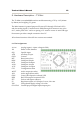
8.1. Rear D-sub Female Connector
2: Data out (from tracker)
3: Data in (to tracker)
5: Ground
8: 1-Wire data bus