Argent Data Systems Tracker3 Family User’s Manual Revised 1-3-2014 Argent Data Systems, Inc. PO Box 579 Santa Maria, CA 93456-0579 USA (800) 274-4076 / +1 805 619-4515 Fax (866) 302-6890 www.argentdata.com Copyright © 2007-2013 Argent Data Systems, Inc.
FCC Part 15 Notice This device complies with Part 15 of the FCC Rules Operation is subject to the following two conditions: this device may not cause harmful interference, and (2) this device must accept any interference received, including interference that may cause undesired operation. This equipment has been tested and found to comply with the limits for a Class B Digital Device, pursuant to part 15 of the FCC Rules.
Tracker3 User’s Manual 1. 2. 3. 4. 5. 1 Introduction .............................................................................................................. 3 A Brief Overview of APRS...................................................................................... 3 Where the Tracker3 Fits In...................................................................................... 5 Major Features .....................................................................................................
Tracker3 User’s Manual 2 17.7. Configuration Profiles ............................................................................... 23 17.8. Loading and Saving Settings.................................................................... 23 17.9. Basic Configuration Options .................................................................... 23 17.10. Tuning and Diagnostics ............................................................................ 29 17.11. Access List .................................
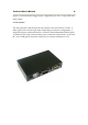
Tracker3 User’s Manual 3 1. Introduction The Tracker3 family includes the stand-alone OT3m model, the T3-135 internal board for the Alinco DR-135T, the embeddable T3-Mini board, and the T3-301 with integrated 5-watt transceiver. All of these models share the same software features, with minor differences. This manual covers all Tracker3 variations. The Tracker3 is a packet radio interface focused on APRS™ applications, including position reporting, messaging, and telemetry.
Tracker3 User’s Manual 4 connection and a radio, pass traffic from the radio network to a shared, worldwide APRS stream. Many IGates will pass at least text message traffic, and sometimes other data, from the Internet back to the radio network. In this way, text messages can be passed from one station to another even when a digipeater path between the two doesn’t exist or isn’t reliable.
Tracker3 User’s Manual 5 Another option is an APRS-capable radio, like those sold by Kenwood and Yaesu. These radios have a text display, but require a mapping GPS receiver to display the positions of other stations graphically. An ordinary radio with a TNC can be used in conjunction with a laptop computer or PDA to provide full APRS functionality, including mapping and messaging, although this is usually the most expensive option and may not be practical to operate while driving. 3.
Tracker3 User’s Manual 6 4. Major Features APRS Tracker - The Tracker3 is first and foremost a full-featured APRS tracker. It works with GPS receivers using either the industry-standard NMEA format ($GPRMC, $GPGGA, and $GPGLL sentences) or the proprietary Garmin binary protocol.
Tracker3 User’s Manual 7 Telemetry – All Tracker3 models include an integrated temperature sensor. The OT3m and T3-301 can measure and report their supply voltage, and the OT3m includes four analog 0-20v inputs and one digital telemetry input. The T3-Mini has a total of 13 digital input/output pins and four analog inputs. Temperature and voltage readings can be reported in status packets, and the other readings can be reported in an APRS telemetry message.
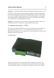
Tracker3 User’s Manual 8 inputs, a counter/transmit trigger input, a digital I/O pin, and a 7-amp solid state relay output. 5.2. Rear Panel The rear panel has a female 9-pin D-sub connector for connection to a radio. A male 9-pin D-sub connector provides, depending on software configuration, a single RS-232 port with hardware flow control or dual independent RS-232 ports. A standard 2.1x5.
Tracker3 User’s Manual 6. Connections 6.1. SERIAL Connector 2: 3: 4: 5: 7: 8: Data in (port A) Data out (port A) Power output for GPS Ground Data out (port B) or CTS Data in (port B) or RTS Note: The serial interface is configured as DTE (data terminal equipment) to allow direct connection to a GPS receiver. Connection to a PC requires a nullmodem cable. 6.2. RADIO Connector 1: 2: 3: 5: 6: 7: 8: Audio out COR / Squelch input PTT out Audio in Ground Power in PTT in 6.3.
Tracker3 User’s Manual 10 7. Jumper Settings A jumper block on the OT3m board provides the following settings: Voltage select – ‘5’. Connects pin 4 of the serial connector to the output of the 5-volt regulator. Use this setting to supply power to a 5-volt GPS receiver or other external device. Voltage select – ‘12’. Connects pin 4 of the serial connector to the input of the 5-volt regulator.
Tracker3 User’s Manual 11 8. Hardware Description – T3-135 The Tracker3 model T3-135 is a plug-in board for the Alinco DR-135T. It can also be used with the DR-235 and DR-435 models. To install the board, disconnect power to the radio and remove the four screws holding on the bottom cover plate. A multi-colored cable connects the rear connector to the radio’s main board.
Tracker3 User’s Manual 12 9. Hardware Description – T3-Mini The T3-Mini is an embeddable tracker module measuring 1.72" by 1.12" (43mm by 28mm) and weighing 5.5 grams. The Mini features 13 general-purpose I/O pins (GP1 through GP12 and AUX) and four analog inputs. Connections are made through 34 contacts in two rows of 17, with a pitch of 0.1" and row spacing of 1" center to center. A mini USB type B connector provides a simple connection for a PC.
Tracker3 User’s Manual 13 10. Hardware Description – T3-301 The T3-301 is a Friendcom FC-301/D 5-watt data radio module with a Tracker3 series board installed. The tracker takes over the module’s 9-pin D-sub connector – its pin assignments are not the same as the as the bare FC-301/D radio, and the Friendcom programming software and cable should not be used with the T3-301. Configuration of the radio’s frequency and power settings is accomplished through the tracker’s command line interface.
Tracker3 User’s Manual 10.2. 14 Radio Configuration Two special commands are available from the T3-301’s command line for setting the radio frequency and power: SETFREQ ttt.ttt rrr.rrr sets the transmit frequency (ttt.ttt) and receive frequency (rrr.rrr) in MHz. Note that the frequencies must be entered in exactly the format specified, e.g. “SETFREQ 144.390 144.390”. SETPOWER <1-5> sets the transmitter power (approximately) in watts.
Tracker3 User’s Manual 15 11. Setup and Configuration You can use a PC to connect to the Tracker3 either the Windows configuration program (otwincfg.exe) or a terminal emulation program of your choice, such as HyperTerminal, PuTTY (available from http://www.putty.org), or Minicom. To use the command console, connect at the proper baud rate (4800 baud is the default) and press enter several times until you see a command prompt. When using the USB port, the baud rate setting is ignored.
Tracker3 User’s Manual 16 Other modern operating systems should be able to use the tracker as a generic CDC ACM serial device. Its VID is 0x134A and PID is 0x9000. For current driver files and operating system specific setup instructions for the USB port, please see http://wiki.argentdata.com. 12.
Tracker3 User’s Manual 17 KISS – In KISS mode, a PC or other host device sends and receives raw AX.25 packets. Keep in mind that even with one or both ports in KISS mode, the Tracker3 will continue to perform its other functions, including messaging and digipeating. The host should use a different callsign/SSID combination to avoid interference. WS2300 – Supports LaCrosse WS-2300 series weather stations at 2400 baud, again ignoring manual baud rate settings.
Tracker3 User’s Manual 18 14. Remote Access Commands can be issued to the Tracker3 remotely via APRS messages. The originating station’s callsign must appear in the device’s security authorization list (see AUTHLIST command.) Commands are prefixed with ‘CMD’, and the results of the command, if any, will be send back as an APRS message to the sending station. For example, ‘CMD VERSION’, sent from an APRS client, will cause the target device to reply with its firmware version.
Tracker3 User’s Manual 19 exit safe mode, use the RESET command or power off the tracker after removing the jumper used to enter safe mode. The use of the default configuration is temporary. Normal operation will be resumed when safe mode is exited. To overwrite the active configuration with the saved defaults, use the RESET DEFAULT command. The tracker need not be in safe mode to restore defaults. 16.
Tracker3 User’s Manual 20 Also, should a valid password be sent without being received by the target device, an eavesdropper would know the next valid password. If you are unsure of being able to reach the target device, send an unauthenticated message or query first and make sure you get a reply. 17. Garmin Fleet Management Interface Some Garmin navigation systems provide a Fleet Management Interface (FMI) that can be used with the Tracker3 with the proper cable. See http://wiki.argentdata.
Tracker3 User’s Manual 21 OTWINCFG Configuration Program The Tracker3 can be configured using the otwincfg.exe program under Windows. The program is available for download at http://www.argentdata.com/support. Connect the tracker and start the configuration program. The first window displayed allows you to select the COM port that the tracker is connected to. 17.1.
Tracker3 User’s Manual 17.4. 22 Warm Boot vs. Cold Boot If the unit is already powered on and operating when you click the ‘Connect’ button, the program attempts a ‘warm boot’ operation to put the device into configuration mode. If the firmware has been corrupted, i.e. by a failed upgrade, it may fail to enter configuration mode. You can correct this by performing a ‘cold boot’ - power the unit off and power it on again after clicking ‘Connect’.
Tracker3 User’s Manual 17.7. 23 Configuration Profiles The Tracker3 can store two separate configuration profiles. The profile currently being shown is selected using the tabs at the top of the window labeled ‘Profile 1’ and ‘Profile 2’. When it is first powered on, the Tracker3 will always start out using Profile 1. After startup, profile selection depends on the settings in the profile switching screen. To access these settings, click ‘Profile Switching’.
Tracker3 User’s Manual 24 Alternate Paths - When enabled, this option causes the tracker to alternate between the paths specified in either profile with each transmission. Symbol Table and Symbol Code – These settings control the symbol used to indicate the station’s position when drawn on a map. See Appendix B for a listing of available symbols. Common symbols can be selected using a dropdown menu. Temp. Adjust – Calibration offset for onboard temperature sensor.
Tracker3 User’s Manual 25 Voltage – Report input voltage in the comment field. The maximum value is 18.5 volts, and the minimum is the dropout voltage of the regulator – typically 6.7 volts. Compressed – Enables Base91 compressed position reporting. This mode is widely, but not universally, supported. Packets in Base91 format are shorter than their uncompressed equivalents and provide greater position resolution. Telemetry every n – Sends a telemetry packet every n transmissions.
Tracker3 User’s Manual 26 Use PTT Input – When this checkbox is enabled, the tracker can be connected inline with a microphone to operate in burst-after-voice (mic encoder) mode. A packet will be transmitted whenever the microphone PTT is released. Timeslot – The timeslot option is typically used to coordinate multiple trackers, especially for special events where many transmitters will be sharing the same channel with a high beacon rate.
Tracker3 User’s Manual 27 useful for applications like high altitude balloons that may lose GPS lock after landing, but still need to transmit to be found. Save – When enabled, the tracker will save its last-known GPS position as a permanent fixed position if the GPS fix is lost. This may be used in the case of a temporary digipeater or weather station where a GPS receiver is installed only during setup and is removed to conserve power.
Tracker3 User’s Manual 28 Reset on Transmit – Setting this checkbox causes the counter to reset with every transmission. Hence, the count reported is the number of events since the last transmission. Debounce – This is a delay applied to the counter input. After a counter event is registered, all subsequent events are ignored until the specified time has elapsed. Without a suitable debounce setting, a typical pushbutton could register several events for one press.
Tracker3 User’s Manual 29 No Suppress PTT Out on PTT In – This option allows the tracker to be used in burst-after-voice mode without breaking any lines between the microphone and radio. PTT is not asserted by the tracker until the microphone PTT is released. External Squelch – Enables the use of an external squelch or COR input. Copy from Profile n – This button copies the contents of one profile to the other. 17.10.
Tracker3 User’s Manual 30 17.11. Access List This screen allows editing of the tracker’s remote access control list. 17.12. Profile Switching To access the profile switching setup, click on the ‘Profile Switching’ button from the main configuration screen. The conditions to test are selected using the checkboxes to the left of each condition.
Tracker3 User’s Manual 31 equal to). Clicking on the button showing the comparison operator toggles it between these two settings. The Altitude and Speed values are compared with those indicated by the GPS. Onboard sensors provide readings for comparison with the Temperature and Voltage fields. ADC Input refers to the extra unused analog-to-digital converter input on X1 pin 9. The possible values are 0 to 255, corresponding to a range of 0 to 5 volts.
Tracker3 User’s Manual 32 The ‘Digipeat on my call’ option causes the tracker to repeat packets with the tracker’s own callsign in the packet’s digipeater list. This allows any Tracker3 with the default configuration to be used as a relay if explicitly selected by the sending station. The entries in the alias list specify other digipeater address that the unit should respond to. Only those with the ‘Enabled’ checkbox checked will be used. The ‘Enabled’ option is set in each profile.
Tracker3 User’s Manual 33 18. Command Reference Most commands can be issued through the serial console, APRS message, or fleet management message. Some commands make sense only when used from the local console and are not available for remote access. The Tracker3 will accept command abbreviations. A minimum of three characters must be entered. For example, CALIBRATE can be entered as CAL. AUTOBAUD can be entered as AUTOB, the additional characters being required to distinguish it from AUTOSAVE.
Tracker3 User’s Manual 34 ANALOG Returns the current reading for the specified analog input pin. See the telemetry section of this manual for details on pin assignments. This command is used primarily for scripting. Return value: Current analog reading for specified pin AUTHLIST +/- Displays or changes the list of callsigns authorized for remote access. +callsign adds a callsign to the list, -callsign removes a callsign from the list, and 'none' erases the entire list.
Tracker3 User’s Manual 35 CALIBRATE LOW | HIGH | ALT | PACKET (local only) Calibration functions to set demodulator tuning and transmitter deviation. 'Low' transmits a 1200 hz tone, 'high' transmits a 2200 hz tone, 'alt' transmits alternating 1200 and 2200 hz tones, 'packet' sends a test packet repeatedly, and 'tune' displays a tuning indicator for adjustment of the demodulator. Use the '[' and ']' keys for coarse adjustment of the transmit audio level, and '-' and '+' for fine adjustment.
Tracker3 User’s Manual 36 CUSTSYM on|off Enables the use of custom symbols if they have been uploaded to a compatible Garmin GPS receiver (using the Garmin xImage utility). CWBEACON Sends as a Morse code beacon. (local only) DAO on|off Enables transmission of the !DAO! extended-precision construct. This provides an extra digit of precision over the standard APRS position format, but results in a longer packet and may not be supported by all APRS clients.
Tracker3 User’s Manual 37 ECHO [text] Prints text to the console. Allows output from scripts when using the USB console. EXTSQL on | off Enables external squelch input. EXTTEMP on | off Enables temperature reporting from an external DS18S20 temperature sensor connected to the 1-wire data bus. FAHRENHT on|off Reports temperatures in Fahrenheit when temperature output in the status text is enabled. FILTER on | off When FILTER is ON, the MONITOR command will only output printable characters.
Tracker3 User’s Manual 38 Selects transmission baud rate. Note that the reception baud rate is fixed at 1200 baud. Return value: 99 = invalid setting, 0 = 1200, 1 = 300, 2 = PSK31 HEADERLN on|off Breaks MONITOR packets into two lines, with header and payload separated. HOPLIMIT For digipeater alias (1-8), sets the maximum number of digipeater hops allowed. This can be used to limit excessively long paths that may cause network degradation.
Tracker3 User’s Manual 39 PASSALL on|off Normally the Tracker3 ignores all received packets that fail a frame check sequence test. PASSALL disables the FCS test. This option should only be used for troubleshooting as it will result in output of corrupted packets. PASSLIST [n] (local only) Generates a list of the next n one-time passwords to be used, based on the pass phrase entered with the SECRET command. Default is 144.
Tracker3 User’s Manual 40 PROFILE 1 | 2 Selects the configuration profile to use. If profile switching is enabled, the profile switching parameters will still be in effect. PROPWPT on|off Enables proprietary waypoint strings. With PROPWPT OFF, output formats are $GPWPL and $PGRMW. With PROPWPT ON, $PKWDWPL, $GPWPT, and $PMGNWPL are output. PTTINPUT on|off Enables PTT input for mic encoder opration. A position packet will be transmitted when the mic PTT is released. OT3m model only.
Tracker3 User’s Manual 41 REQALL on|off Require all configuration switch parameters to be met before switching profiles. RESET Perform software reset. Saved settings are unaffected. RING on|off Sends a bell character whenever an incoming message arrives. SCRIPT on|off Enables the script engine. SECRET Sets the pass phrase for the one-time password authentication system. SEND Sends a text message to the designated recipient.
Tracker3 User’s Manual 42 The and settings define these two limits. For storage efficiency, the speeds are represented in units of 32 centimeters/second. To convert from miles per hour, multiply by 1.397. To convert from kilometers per hour, divide by 1.152. Setting MPH Km/h 5 3.6 5.7 10 7.2 11.5 15 10.7 17 25 17.9 29 40 28.6 46 60 43 69 80 57 92 100 71 115 and are specified in seconds.
Tracker3 User’s Manual 43 STATUS <0-255> Status packets are sent every n transmissions, or if set to 0, status text is sent as part of the position packet. SYMBOL <1-2 characters> APRS symbol character, optionally preceded by symbol table or overlay identifier. TELEMETRY on|off Enables transmission of telemetry packets. TEMP on|off Enables transmission of temperature readings from the on-board temperature sensor. TEMPADJ <-128 to 127> (degrees C) Offset for temperature sensor in degrees C.
Tracker3 User’s Manual 44 TXLEVEL <1-255> Sets transmission audio level. This value should be selected to provide an appropriate FM deviation level, typically about 3.5 kHz. TXNOFIX on|off Allows transmission of last position if GPS fix is lost for more than 30 seconds. Default behavior is to cease transmitting the position in the absence of a valid GPS signal. TXONCHG on|off Causes an immediate transmission when switching configuration profiles. USEALIAS on|off Enables digipeating for alias n.
Tracker3 User’s Manual 45 19. Telemetry All Tracker3 models have the ability to send telemetry information from their onboard sensors, and some models include external analog and digital telemetry inputs.
Tracker3 User’s Manual 46 20. Script System The Tracker3’s script engine allows simple programs to be run on the tracker to customize the tracker’s operation and automate tasks. Use the ‘script’ button in the otwincfg utility to access the script editors. Common script tasks include handling multiple beacon texts, responding to events such as door alarms or high temperatures, transmitting APRS objects or telemetry parameters, and changing regional settings automatically.
Tracker3 User’s Manual 47 The highlighted line in the script listing shows where the next command will be inserted. The 'Delete Line' button deletes the currently selected line, and the 'Up' and 'Down' buttons move the line in the listing. Conditional commands cause automatic indentation in the listing. The numbers directly under the listing show the amount of script memory used. Commands that accept one or more parameters use the values in the A, B, C, T, X, Y, area corners, and flags fields.
Tracker3 User’s Manual 48 To compare the current altitude to a fixed value, for example, you can select "Altitude" in box A and enter "10000" in box C, and click the "If A > C" button to create the line "If Altitude > 10000". The next command entered will be indented, indicating that it will only be executed if that condition is true. The "End Block" command ends the conditional statement. "Else" reverses the sense of the last conditional statement and should be used before the closing "End Block". 20.2.
Tracker3 User’s Manual 49 On Startup Executes a block of code only once, immediately after the tracker is powered on. On Second Executes a block of code once per second. On Interrupt Executes a block of code whenever a low-going edge is detected on the CT (counter/trigger) pin. On GPS Fix Executes the following block whenever a valid GPS position fix is obtained. Set A = B Sets a counter to the value in another counter. Set A = C Sets a counter to the value specified in box C.
Tracker3 User’s Manual 50 Use this command carefully - the tracker's flash memory has a write endurance of about 100,000 cycles, and any command that changes a value in the tracker's configuration will require a flash write. At 8 script executions per second, an errant script could wear out the flash memory in a few hours. Flash writes also cause the received packet buffer to be discarded. Use flags or ‘Do Once’ to avoid executing the same command repeatedly.
Tracker3 User’s Manual 51 These general-purpose counters have no predefined meaning, and they have no effect on the rest of the system. Ticks This counter increments every 1/1200 second, and counts from 0 to 1199. TX Counter Seconds elapsed since the last automatic transmission. Second This counter indicates the second of the current hour (synchronized to GPS time) from 0 to 3599. Pulse Count This counter is used by the event counter function described elsewhere in this manual.
Tracker3 User’s Manual 52 21. UI-View32 Setup For use with the UI-View32 APRS client, either port of the Tracker3 can be set manually to KISS mode. No configuration commands are needed in UI-View32 once this has been accomplished. In this example, port A has been set to KISS mode at 9600 baud using the tracker configuration utility. The console commands AMODE KISS and ABAUD 9600 produce the same result.
Tracker3 User’s Manual 53 No ‘Into KISS’ or ‘Exit KISS’ commands are needed, and any settings in these fields should be deleted. Placing a ‘0’ in the ‘Exit KISS’ field avoids a bug in UI-View32 that prevents it from exiting properly when the option is left blank.