
User manual


RP6 ROBOT SYSTEM - 4. Programming the RP6
void moveAtSpeed(uint8_t desired_speed_left, uint8_t desired_speed_right)
This function adjusts the setpoint speed. Both parameters will define the desired
speed for the left and right motor. Frequently calling the motionControl function (as
described in the previous chapter) results in regulation of the speed to the setpoint
values. Setting these values to zero, initiates a slowdown, followed by complete deac-
tivation of the PWM modules.
getDesSpeedLeft() and getDesSpeedRight()
These macros allow you to read the actual setpoint speed values.
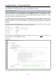
Usage is quite simple as you can see in the following example program:
1
2
3
4
5
6
7
8
9
10
11
12
13
14
15
16
17
18
#include "RP6RobotBaseLib.h"
int main(void)
{
initRobotBase(); // Initialize the Microcontroller
powerON(); // Activate Encoders & Motor current sensors (IMPORTANT!)
moveAtSpeed(70,70); // set desired speed
while(true)
{
// Frequently call the motionControl function from the
// main loop – it will adjust both motor speeds:
task_motionControl();
task_ADC(); // has to be called for Motor current sensors!
}
return 0;
}
... and now RP6 will start moving directly! Of course the robot will not react on any
obstacles and is moving forwards only! The system will only try to regulate the speed
level and automatically adjust motor power – e.g. in ascending or descending a ramp.
BE CAREFUL: This behaviour may be very dangerous for your
own fingers – Take care to keep your fingers away from the cater-
pillar tracks and wheels, and keep clear of the area between printed
circuit board and the caterpillar tracks! There is a considerable risk
of injury! As already explained, the motor power will automatically
be increased and the motors are quite powerful!
Speed parameters for the moveAtSpeed function is not specified in cm/s or equivalent
units, but in a rotational Velocity unit.
After all, the robot's speed depends on the real circumference of caterpillar tracks and
wheels or in other words the encoder's resolution. There are considerable tolerances
from 0.23 up to 0.25mm for each encoder segment. Thus the Encoder resolution has
to be measured!
The system will measure the rotational speed at intervals of 200ms which is equival-
ent to a rate of 5x pro second. So the unit is “Encoder Segments per 200ms”. A value
of 70 as it has been used in the example on the previous page has to be interpreted
- 99 -