
User manual


RP6 ROBOT SYSTEM - 2. The RP6 in detail
2.1.1. Bootloader
There is a so called Bootloader located in a special memory area of the
microcontroller. This tiny program is responsible for loading new user programs into
the microcontroller's memory via the serial interface. The Bootloader communicates
with the the RobotLoader software (original name was RP6Loader) on the host PC.
Like this, no additional programming hardware is required. The USB Interface can be
used for communication with the controller through text messages and additionally to
program the controller. However there is one drawback in using a Bootloader: it needs
2KB of the flash memory, which will leave 30KB free memory for your own programs.
This does not bother us too much as there is plenty of room even for very complex
programs (compared to the 7KB free memory of the tiny ASURO robot)!
2.2. Power Supply
Of course the robot needs energy. The RP6 is carrying this energy in form of 6 accu-
mulator batteries. Operating time will heavily depend on battery capacity and al-
though the electronic systems will consume relatively small amounts of energy the
bulk load of energy will end up in the motors, depending on their load.
In order to provide long operating times you might favour batteries with ample capa-
cities of up to 2500mAh. Capacities of 2000mAh however will be useable as well. High
quality batteries will provide between 3 to 6 operating hours, depending on motor
load and battery quality. You will need 6 batteries, summing up to a voltage of 6x
1.2V = 7.2Volts. The block schematic diagram labels this battery voltage "UB" (= "U-
Battery", U is the standard letter for voltage in electrical engineering formulas). "UB"
is defined as a nominal voltage only, as the voltage may vary over time. Completely
charged NiMH batteries can deliver up to 8.5V! The voltage drops while the Battery is
discharged and may change drastically, depending on load and quality as well. The
critical value for this is the internal resistance.
Of course, an altering supply voltage is not useable for sensor measurements. More
important however is the limited operating voltage range of semiconductor compon-
ents. The microcontroller for instance might be destroyed by applying voltages too
high over 5V. Therefore we have to reduce and stabilize the voltage level to a well
defined level.
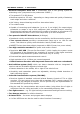
This is performed by an integrated voltage regulator capable of
supplying a current up to 1.5A (see figure). At 1.5A this device
would dissipate a lot of heat and therefore it is attached to a
large copper plane on the PCB. Even with this heat sink we sug-
gest to limit currents over 1A to a few seconds only. Otherwise
you will have to attach an additional heat sink.
Continuous current load should be limited to about 800mA. Such
a heavy load would quickly discharge batteries anyway.
Under normal load conditions and without expansion modules
the robot will not draw more than 40mA, unless the IRCOMM
transmitter is active. This current level will not cause any problems for the regulator
and it can supply enough power for lots of expansion board. Usually the expansions
will need something in the range of 50mA, if no motor loads, power LEDs, etc. are
used on them.
- 19 -