
User manual


RP6 ROBOT SYSTEM - APPENDIX
Make sure that you check if your Hardware uses the correct voltage levels. It must be
5V TTL – if it is standard RS232 then it will be +-12V which could damage the pins. In
this case you need a RS232 level shifter like the MAX232 or similar. In the same way
you have to use a proper 3.3V level shifter if you use low voltage devices.
If you want to use the Bootloader you have to connect MRESET to the RTS pin. The
other pins are usually not required. Except maybe the VTARGET / +5V Pin for supply
of level shifters. Small devices with up to 200mA power consumption can be directly
powered from this pin.
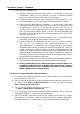
ADC Connectors:
The figure shows the pin assignments for both free ADC channel connectors.
We did not assemble these connectors and you
may apply use 3-pin connectors with 2.54mm
grid. Be careful in soldering and do not ruin the
mainboard! If you are unexperienced with sol-
dering, please refrain from soldering at the main-
board and prefer to start experiments by using
an expansion board!
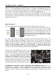
You may connect any two analog or digital sensors to these free ADC channels. The
sensor's output voltages are allowed to range from 0 up to 5V and the connectors
provide the sensors with the 5V supply voltage. On the new RP6v2 there is already a
220µF electrolytic capacitor in the power supply line. On the old RP6 it might be wise
to solder a big electrolytic capacitor to the mainboard – values from 220 up to a
470µF (do not exceed this value! The capacitor's operating voltage should be bigger
or equal to 16V) will be perfectly suitable for most applications.
However you will probably not really need a
big electrolytic capacitor, unless you are work-
ing with sensors, which require vast peak cur-
rents – e.g. the popular Sharp IR distance
sensors. Decoupling capacitors (100nF) on the
mainboard are suitable for short connection
wires only – for long wires, these have to be
directly soldered to the sensor (we advise to
directly mount these capacitors at the sensor's
connection pads even for short wires as well!).
ATTENTION: The Pinout is NOT compatible with standard Servos! This is on
purpose as you need some power supply filtering for most Serovs anyway (LC Low-
pass Filter for example – so for example 10 to 100µH ferrite core high power
inductor / choke in series and 220µF capacitor parallel after the inductor close to the
servo).
- 136 -